Assembled gas sensor calibration apparatus

A sensing standard and component-based technology, applied in measuring devices, analyzing gas mixtures, standard gas analyzers, etc., can solve problems such as low installation and use efficiency, inconvenient operation and carrying, and influence on atmosphere monitoring, and achieve easy operation, Easy loading and unloading, high efficiency

Pending Publication Date: 2017-06-27
GENERAL ENG RES INST CHINA ACAD OF ENG PHYSICS
View PDF9 Cites 5 Cited by
  • Summary
  • Abstract
  • Description
  • Claims
  • Application Information

AI Technical Summary

Problems solved by technology

The calibration results of this sensitive gas component calibration device have certain limitations, because the signal conditioning circuit and the sensitive gas component are not in the same container, and the signal conditioning circuit changes with the ambient temperature, humidity, pressure, etc. Affect the results of atmosphere detection
[0003] When the gas sensor calibrated by the calibration device for sensitive gas components is used in the actual environment in the form of components, when the calibrated sensitive gas components and the signal conditioning circuit constitute a component-type atmosphere sensor for monitoring the trace atmosphere in a closed environment, the signal conditioning circuit is under pressure. , temperature, humidity, etc., will interfere with and affect the results of atmosphere monitoring, which will affect the qualitative analysis of trace gas atmosphere changes on the corrosion and erosion of products or component materials
Due to the small size of the sensitive components, it is necessary to design corresponding supporting tooling, and the installation and use efficiency in actual work is relatively low. In addition, there are pressure gauges, thermometers, etc. installed outside the container. When a third-party calibration is required, pressure gauges, The thermometer is protected, which brings a lot of inconvenience to operation and carrying

Method used


Image

  • Assembled gas sensor calibration apparatus
  • Assembled gas sensor calibration apparatus
  • Assembled gas sensor calibration apparatus

Examples


Embodiment Construction

[0019] The present invention will be further described below in conjunction with accompanying drawing:

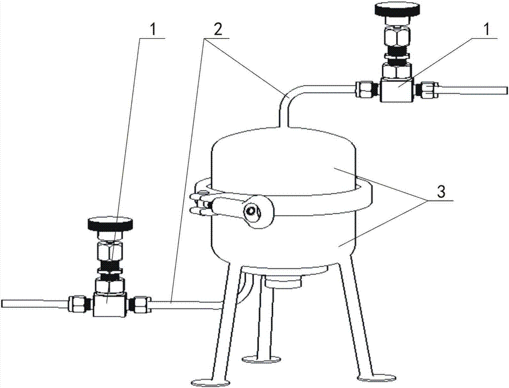
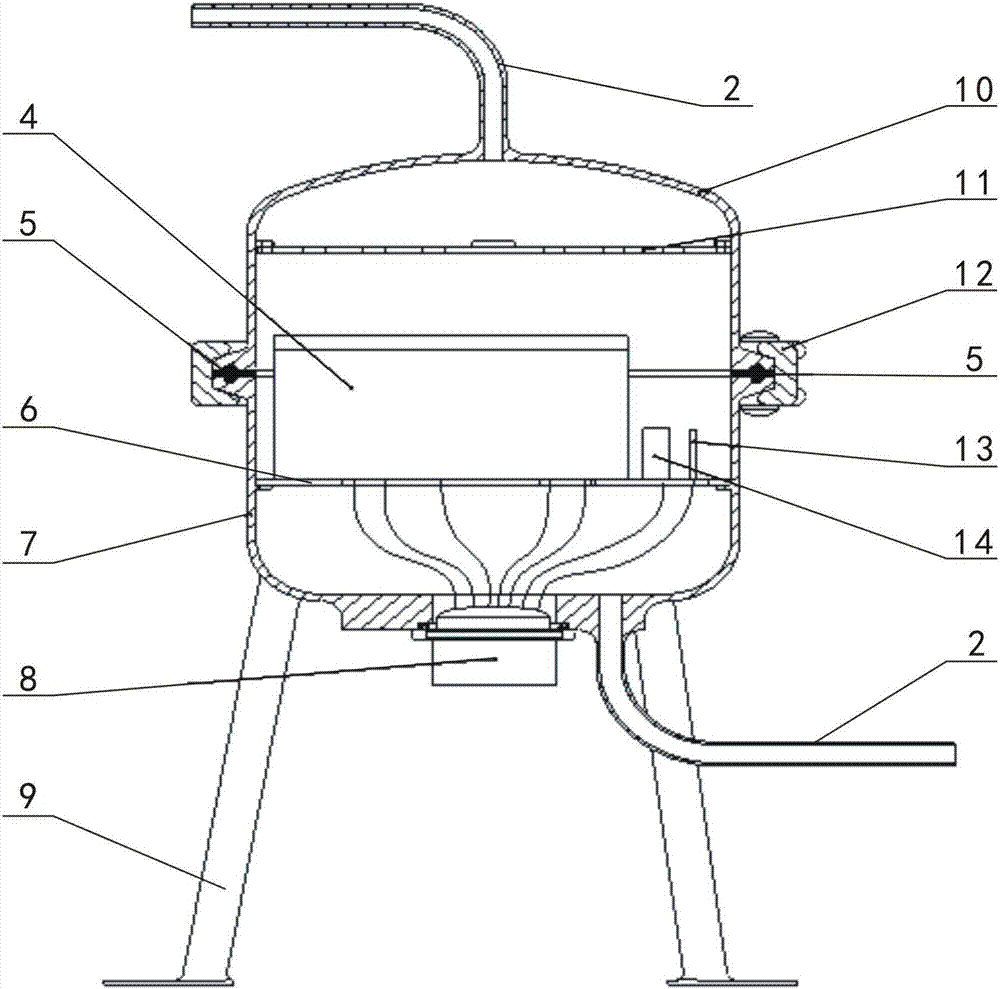
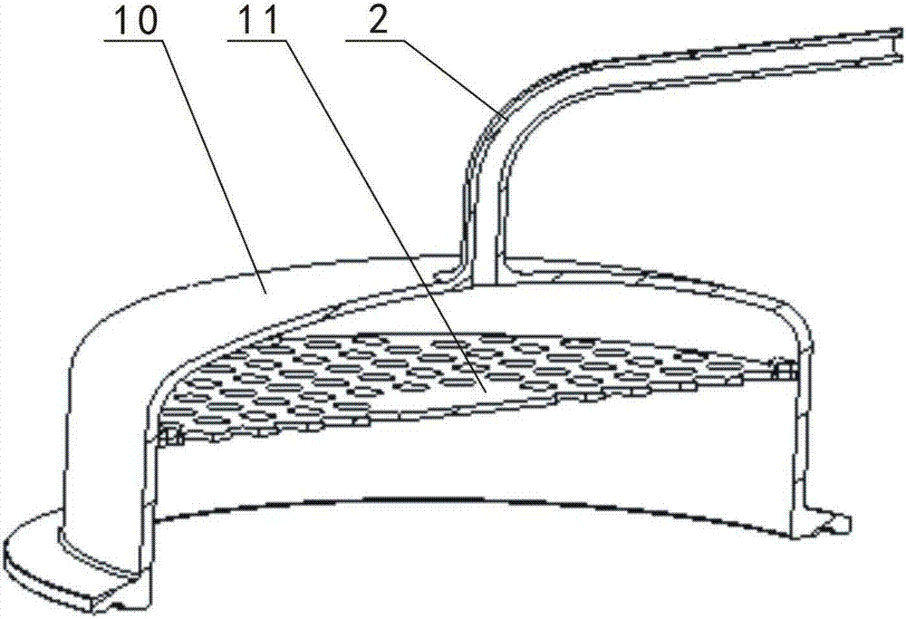
[0020] Such as Figure 1-Figure 6 As shown, the component type gas sensing calibration device 3 of the present invention includes an upper sealed tank 10, a lower sealed tank 7, an air distribution plate 11, a clamp 12, a sealing ring 5, a device mounting plate 6, a gas test component 4, a temperature The sensor 13, the pressure sensor 14 and the wire connector 8, the gas test assembly 4 is an assembly formed by installing the signal conditioning circuit and the gas sensitive element in a metal box and encapsulating the signal conditioning circuit with silicone gel. The upper part of the airtight tank 10 is provided with an air pipe 2 for air intake and a valve 1 is installed on the air pipe 2, and a plurality of vertical air holes 111 with a diameter of 1.5 to 3 mm are provided on the horizontal air distribution plate 11. The air flow distribution plate The central positi...


PUM


Abstract

The invention discloses an assembled gas sensor calibration apparatus. A signal conditioning circuit and a gas sensitive element are installed in a metal box and the signal conditioning circuit is packaged by pouring of organic silicon rubber so that a gas testing assembly is formed. A gas distribution plate is mounted in an upper sealed casing; a conductor wire connector is mounted on the lower portion of a lower sealed casing. The gas testing assembly, a temperature sensor and a pressure sensor are respectively mounted on a device mounting board in the lower sealed casing and are connected with the conductor wire connector through conductor wires. The upper sealed casing and the lower sealed casing are in sealed connection through a sealing ring and a clamping hoop. The assembled gas sensor calibration apparatus has the advantages of solving the problem that the signal conditioning circuit is damaged due to inflammability and explosibility of hydrogen, avoiding abnormal response of the sensors due to over-high flow of gas or due to the fact that the gas flow directly blows to the sensitive element, and being simple and convenient to operate and convenient to carry.

Description

technical field [0001] The invention relates to a gas sensing calibration device including a gas sensor, in particular to a component type gas sensing calibration device. Background technique [0002] Gas sensors are widely used in electronics industry, automobile industry, metallurgical industry, petrochemical industry, float glass, fine organic synthesis, aerospace, food processing, etc. , It is easy to leak during transportation and use, and hydrogen is not conducive to breathing, it is colorless and odorless, and cannot be detected by the human nose, especially the ignition point of hydrogen is only 585°C. If the hydrogen content in the air reaches more than 4%, it may explode when exposed to an open flame. Therefore, in an environment where hydrogen may be produced, a hydrogen sensor must be used to detect the hydrogen content in the environment and monitor its leakage. The calibration method or device of the existing gas sensor generally uses the gas distribution sys...

Claims


Application Information

Patent Timeline
Patent Type & Authority Applications(China)
IPC IPC(8): G01N33/00
CPCG01N33/0006
Inventor 季锡林聂飞张奇陈练杜寿兵王祎玮宁菲
Owner GENERAL ENG RES INST CHINA ACAD OF ENG PHYSICS
Why Eureka
Try Eureka