
A terahertz lens based on a metal plate

A terahertz lens and metal plate technology, applied in the field of terahertz lenses, can solve the problems of difficult precision control, dangerous operation, etc., and achieve the effects of small dispersion, easy fabrication, and simple structure

Active Publication Date: 2018-05-18
CHINA JILIANG UNIV
View PDF5 Cites 0 Cited by
  • Summary
  • Abstract
  • Description
  • Claims
  • Application Information

AI Technical Summary

Problems solved by technology

This article proposes that the metal sheets are arranged in parallel at equal intervals according to the phase distribution, and at the same time, each metal sheet is etched into an arc shape with a different curvature radius by chemical corrosion method, and each metal sheet with a different curvature radius is arranged in parallel to produce a focusing effect , this method of arranging metal sheets in parallel is simpler than the previous method, but the experimental method of chemically etching metal plates has the disadvantages of dangerous operation and difficult control of precision

Method used


Image

  • A terahertz lens based on a metal plate
  • A terahertz lens based on a metal plate
  • A terahertz lens based on a metal plate

Examples


Embodiment 1

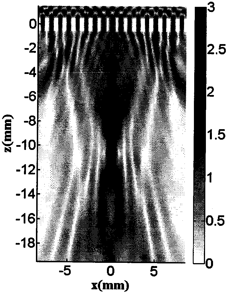
[0029] Design a working wavelength as λ d = 1 mm, Φ 0 =1.66π, lens example with focal length f=10mm, period p=1mm, composed of eighteen metal plates, with seventeen metal plate gaps, according to the propagation constant formula and the phase distribution formula, the d corresponding to the phase is calculated value, as shown in Table 1 below.

[0030] Table 1

[0031]

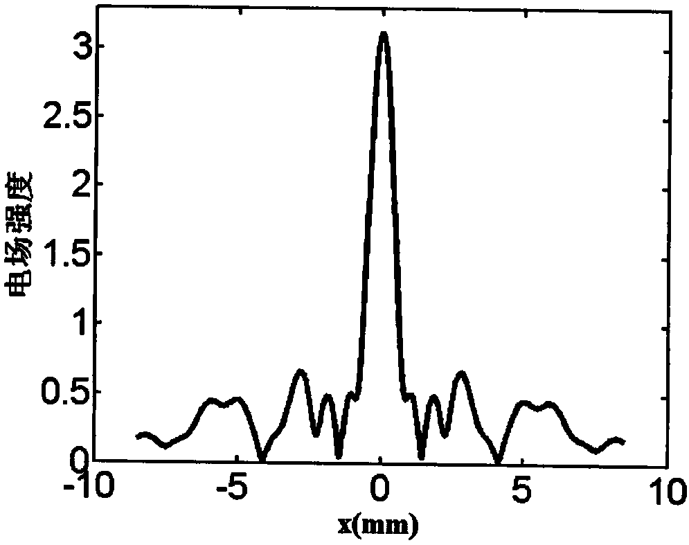
[0032] Arrange the metal plates in parallel according to the corresponding relationship in Table 1, resulting in Figure 4 The electric field strength distribution shown. Figure 4 The xz section electric field distribution diagram obtained when the focal length of the terahertz lens is designed for embodiment 1 of the present invention is f=10mm, it can be seen from the figure that the electromagnetic wave propagates through the terahertz lens based on the metal flat plate in this embodiment (the port is at z= 0.5mm) and began to converge, and at z = 10.5mm can be observed obvious focusing pheno...

Embodiment 2

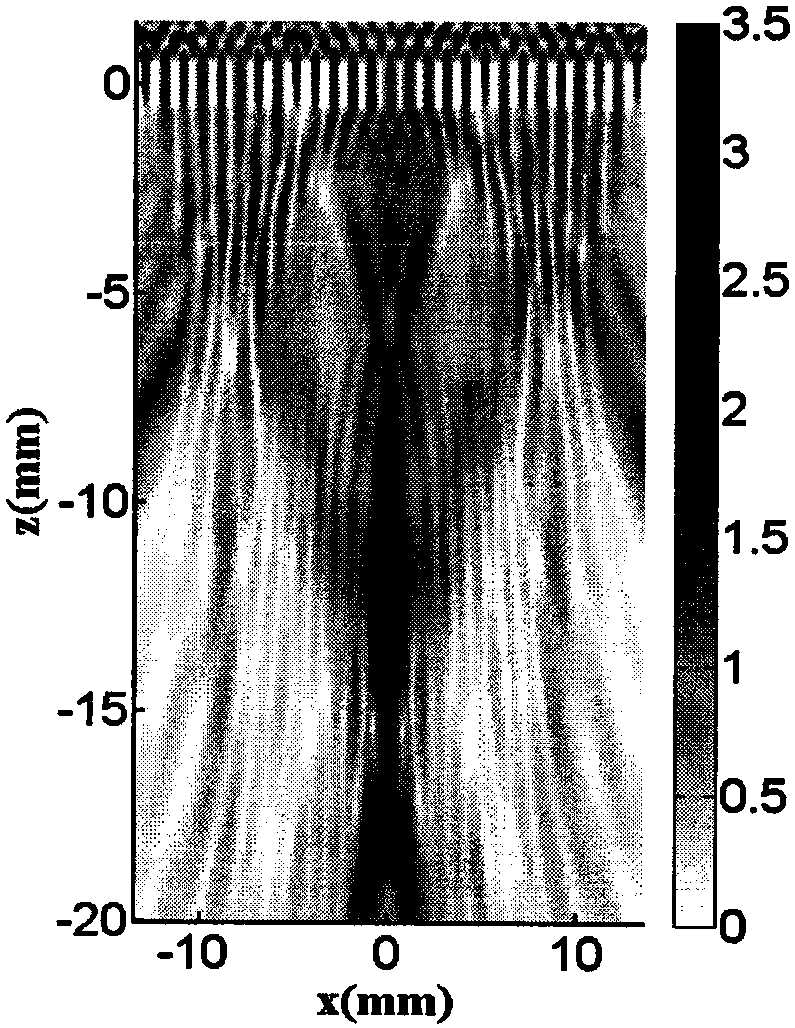
[0034] In another specific embodiment of the present invention, design a working wavelength as λ d = 1 mm, Φ 0 =1.66π, lens example with focal length f=15mm, period p=1mm, composed of twenty-eight metal plates, with twenty-seven metal plate gaps, calculated by the propagation constant formula and the phase distribution formula corresponding to the phase The value of d is shown in Table 2 below.

[0035] Table 2

[0036]

d 0

d 1

d 2

d 3

d 4

d 5

d 6

d 7

d 8

d 9

d 10

d 11

d 12

d 13

x(mm)

0

±1

±2

±3

±4

±5

±6

±7

±8

±9

±10

±11

±12

±13

Φ(π)

1.66

1.56

1.39

1.07

0.61

0.04

1.35

0.55

1.66

0.67

1.6

0.46

1.24

0

d(mm)

0.9

0.82

0.695

0.59

0.525

0.5

0.677

0.52

1.66

0.531

0.83

0.514

0.637

0.5

[0037] Arrange the metal plates in parallel according to the corresponding relationsh...


PUM


Abstract

The present invention discloses a terahertz lens based on metal plates. The lens comprises at least three metal plates with parallel arrangement, unequal intervals and consistent length, filling materials among the metal plates and supports of the metal plates. The thickness and the length of each metal plate are commonly decided by the polarization state of incident light and the phase distribution requirement of the lens. The work process of the lens comprises as follows: terahertz wave band electromagnetic wave signals output by a power supply are subjected to objective lens collimation and linear polaroid polarization conversion to become collimation parallel linear polarization beam, the beam is irradiated to the lens to generate focusing, and finally, the optical signals after focusing are received by a receiver. The terahertz lens based on the metal plates is small in dispersion, low in ohmic loss, high in coupling efficiency and simple in structure compared to a traditional geometry lens.

Description

technical field [0001] The invention relates to a terahertz lens based on a metal flat plate, and relates to the field of waveguides. Background technique [0002] Terahertz technology is rated as one of the "Ten Technologies that Will Change the Future World" by the United States, and is listed as the first among the "Ten Key Strategic Objectives of the National Pillar" by Japan. In almost all terahertz systems, lenses are required for collimation and focusing to meet the requirements of system linearization and compactness. The lens is especially used in the transceiver front end of the terahertz imaging system, which plays a role of focusing the light beam and plays a very important role in the terahertz imaging system. Metal has a very high dielectric constant in the terahertz band, which is equivalent to a perfect electric conductor (Perfect Electric Conductor, PEC). Terahertz radiation cannot penetrate conductive objects, and electromagnetic waves are almost completel...

Claims


Application Information

Patent Timeline
Patent Type & Authority Patents(China)
IPC IPC(8): G02B3/00
CPCG02B3/00
Inventor 郎婷婷吴梦茹韩张华
Owner CHINA JILIANG UNIV
Learn More