Rotary rolling forging device for gyrorotor forging

A technology of revolving body and forgings, applied in forging/pressing/hammer devices, forging presses, forging presses, etc., can solve the problems of discontinuous forging deformation, low material utilization rate, uneven structure, etc., to achieve continuous internal deformation, material The effect of improved utilization and uniform internal organization

Inactive Publication Date: 2017-06-30
AVIC BEIJING INST OF AERONAUTICAL MATERIALS
7 Cites 0 Cited by

AI-Extracted Technical Summary

Problems solved by technology

[0004] The object of the present invention is to overcome the above-mentioned shortcomings of the prior art, and provide a rotary rolling forging device fo...

Abstract

The invention relates to a rotary rolling forging device for a rotary forging, comprising a rotating shaft (2), on which a left rotating rotor (3) and a right rotating rotor (4) are sleeved, and the rotating shaft ( The two ends of 2) are installed on the fixed sleeve (1) through interference fit, and the fixed sleeve (1) is installed on the press (6) through the bolt (5). The rotation centers of the fixed sleeve (1), the left-rotating rotor (3) and the right-rotating rotor (4) coincide, and the press (6) can drive the left-rotating rotor (3) and the right-rotating rotor (4) to move downward ; Place the blank (8) under the left-rotating rotor (3) and the right-rotating rotor (4), the blank (8) is fixedly installed on the lower die (9), and the center of rotation between the blank (8) and the lower die (9) The line coincides with the centerline of rotation (7) of the rotating shaft (2), and the rough platform of the rotary pier of the press drives the blank (8) and the lower die (9) to rotate along the centerline of revolution (7). The tonnage of the press required by the device of the invention is relatively low, the surface quality of the obtained forging is good, and the internal deformation of the forging is continuous, without folding and uniform in structure.

Application Domain

Upsetting pressesSwagging presses +2

Technology Topic

Image

  • Rotary rolling forging device for gyrorotor forging
  • Rotary rolling forging device for gyrorotor forging
  • Rotary rolling forging device for gyrorotor forging

Examples

  • Experimental program(1)

Example Embodiment

[0015] The technical solution of the present invention will be further described in detail below in conjunction with the accompanying drawings and embodiments:
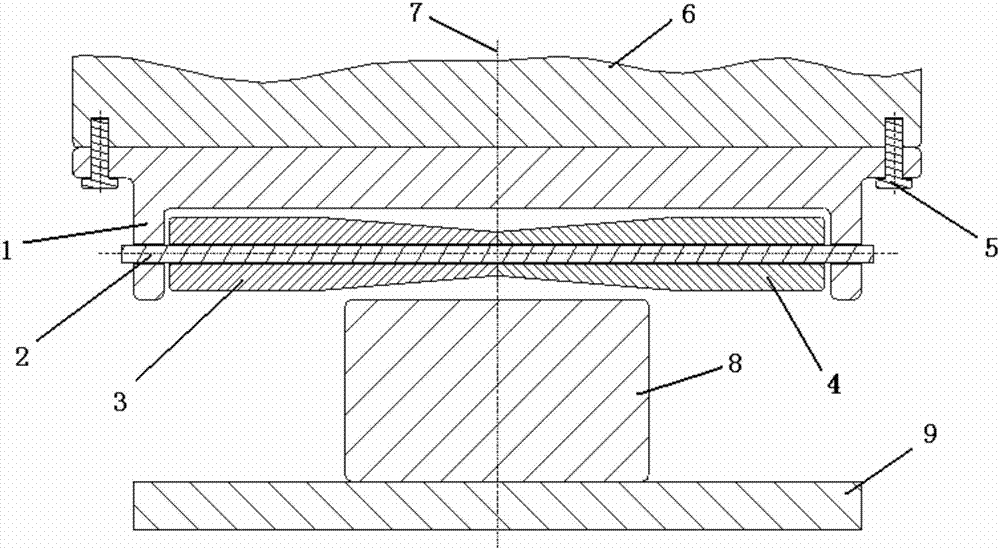
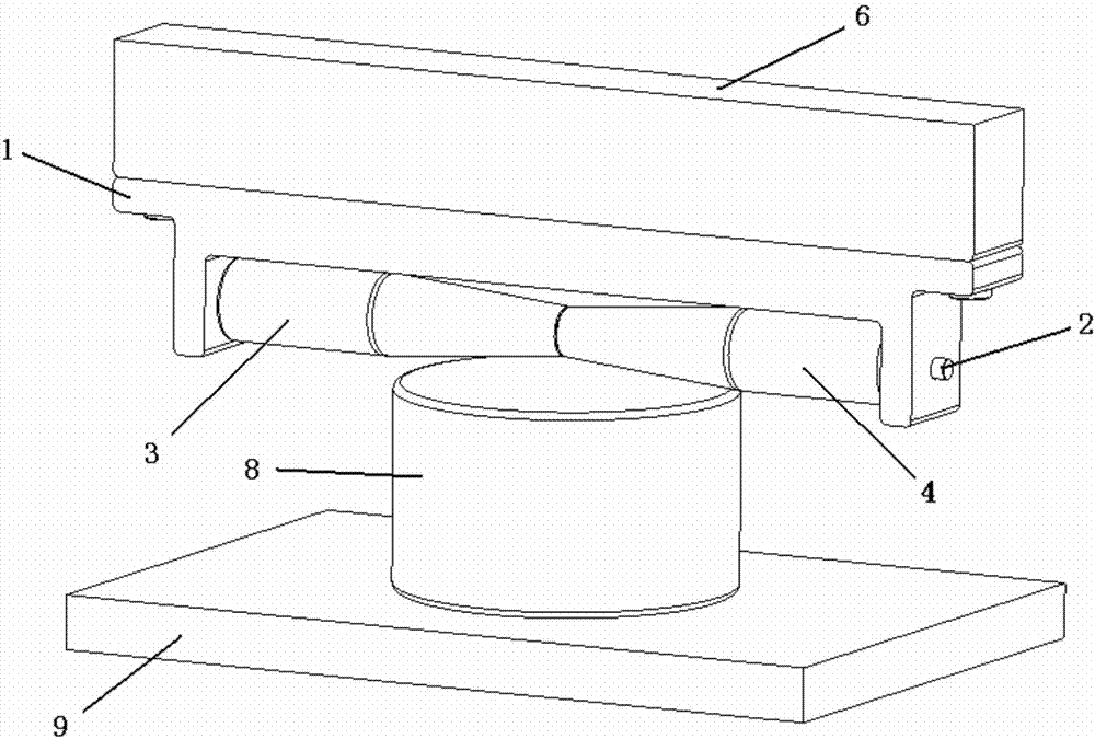
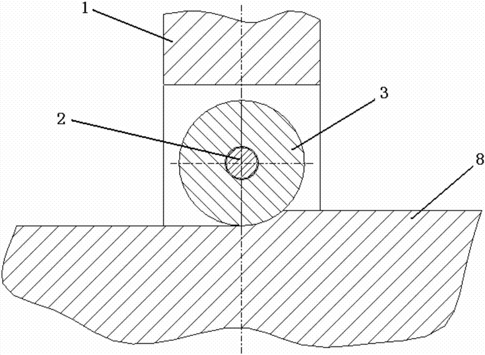
[0016] See attached Figure 1~3 As shown, the rotary rolling forging device of this kind of rotary body forging includes a rotary shaft 2. On the rotary shaft 2, two rotating rotors symmetrical along the rotation center line 7 of the rotary shaft 2 are sleeved, respectively, the left rotating rotor 3 And the right-rotating rotor 4, the left-rotating rotor 3 and the right-rotating rotor 4 are fixed on the rotating shaft 2 through bearings. The two ends of the rotating shaft 2 are installed on the fixing sleeve 1 by interference fit, and the fixing sleeve 1 is installed on the fixing sleeve 1 by bolts 5. On the press 6, the rotation center line 7 of the rotating shaft 2 coincides with the rotation center lines of the fixed sleeve 1, the left rotating rotor 3 and the right rotating rotor 4. The press 6 can drive the left rotating rotor 3 and the right rotating rotor 4 Move down
[0017] A blank 8 is placed under the left rotating rotor 3 and the right rotating rotor 4. The blank 8 is fixedly installed on the lower mold 9. The rotation center line of the blank 8 and the lower mold 9 coincides with the rotation center line 7 of the rotating shaft 2, using a press The rotating pier thick platform drives the blank 8 and the lower mold 9 to rotate along the centerline 7 of rotation.
[0018] The blank 8 in this embodiment is a titanium alloy rotator with a maximum diameter of 600-800 mm. The center of the blank 8 is a solid circular structure or a circular ring structure with a hole in the center.
[0019] During processing, the device of the present invention uses the outer contours of the left-rotating rotor 3 and the right-rotating rotor 4 to shape the upper end surface of the processed revolving body forging, and the blank 8 heated to the initial forging temperature is fixedly installed on the lower die 9. And make the rotation center line of the blank 8 coincide with the rotation center line 7 of the rotating shaft 2, apply lubricant on the upper end surface of the blank 8 in contact with the left rotating rotor 3 and the right rotating rotor 4, and then start the rotating pier of the press 6 The rough table drives the blank 8 and the lower die 9 to rotate along the rotation centerline 7 at an angular velocity ω and at the same time the press 6 presses and moves downwards. When the left rotating rotor 3 and the right rotating rotor 4 lightly touch the blank, the lower speed The forging blank 8 is v1 and the pressing distance is h1. The left rotating rotor 3 and the right rotating rotor 4 rotate in opposite directions. Then the press 6 is raised to make the left rotating rotor 3 and the right rotating rotor 4 and the upper end surface of the blank 8 After disengagement, pressure and move downward again. When the left-rotating rotor 3 and the right-rotating rotor 4 lightly touch the blank, the pressing speed is v2 and the pressing distance is h2 to forge the blank 8. Repeat the above actions to rotate and roll the forging blank 8 until the blank 8 is completely formed.
[0020] The calculation formula of angular velocity ω is as follows:
[0021]
[0022] In the formula: v is the pressing speed of the left-rotating rotor 3 and the right-rotating rotor 4 relative to the blank 8 driven by the press 6, which is 0.05 to 20 mm/s, and Dmax is the maximum diameter of the left-rotating rotor 3 and the right-rotating rotor 4, σ is the rotor coefficient, which is 0.01~0.15.
[0023] Compared with the prior art, the device of the present invention requires a lower tonnage of the press, which can be implemented on ordinary presses such as 2000t and 4000t. It does not need to be polished and repaired during the forging process, and the surface quality of the obtained forgings is better, with internal deformation Continuous, no folding, uniform organization.

PUM

no PUM

Description & Claims & Application Information

We can also present the details of the Description, Claims and Application information to help users get a comprehensive understanding of the technical details of the patent, such as background art, summary of invention, brief description of drawings, description of embodiments, and other original content. On the other hand, users can also determine the specific scope of protection of the technology through the list of claims; as well as understand the changes in the life cycle of the technology with the presentation of the patent timeline. Login to view more.

Similar technology patents

Method for manufacturing titanium-and-titanium alloy high-pressure gas cylinder

PendingCN110465780AEliminate wrinklesReduce roughnessVessel manufacturingPressure vesselsTitaniumHigh pressure
Owner:BAOJI FANMEI MATERIAL TECH

Classification and recommendation of technical efficacy words

Why Eureka
Try Eureka