Closed hydraulic system for heading machine

A technology for hydraulic systems and roadheaders, which is applied to fluid pressure actuating system components, mechanical equipment, fluid pressure actuating devices, etc., can solve the problems of low life of open system components, many impurities in hydraulic oil, and large reversing impact. , to achieve the effect of reasonable and novel structure design, reducing energy consumption and reducing commutation impact

Pending Publication Date: 2017-06-30
无锡华瀚能源装备科技有限公司
View PDF7 Cites 7 Cited by
  • Summary
  • Abstract
  • Description
  • Claims
  • Application Information

AI Technical Summary

Problems solved by technology

[0006] Due to the many impurities in the hydraulic oil, the high temperature, and the large commutation impact, the life of the open system components is low

Method used


Image

  • Closed hydraulic system for heading machine
  • Closed hydraulic system for heading machine
  • Closed hydraulic system for heading machine

Examples


specific Embodiment approach 1

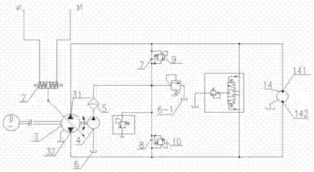
[0021] Specific implementation mode one: as figure 1 As shown, this specific embodiment adopts the following technical solutions: it includes a pilot control device 1, a main oil pump variable mechanism 2, a main oil pump swash plate 3, a charge pump 4, a fine filter 5, a first oil tank 6, and a second oil tank 6- 1. The first one-way valve 7, the second one-way valve 8, the first high pressure relief valve 9, the second high pressure relief valve 10, the oil charge relief valve 11, the motor 14, the motor first port 141, the motor second port Two ports 142, the first oil port 31 and the second oil port 32 of the main oil pump swash plate 3, the main oil pump swash plate 3 is a two-way variable pump, the first oil port 31 on the main oil pump swash plate 3 is connected to the first port 141 of the motor 14 Communication, the second oil port 32 on the main oil pump swash plate 3 communicates with the second port 142 of the motor 14, the pilot control device 1 directly communica...

specific Embodiment approach 2

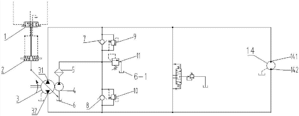
[0023] Specific implementation mode two: as figure 2 As shown, the difference between this specific embodiment and the first specific embodiment is that: the pilot control device 1 is removed, and the variable mechanism 2 is directly controlled by the first control pressure device a1 and the second control pressure device b1, thereby through The control mechanism 2 controls the change of the displacement of the main pump, and other components and connection methods are the same as those in the first embodiment.

specific Embodiment approach 3

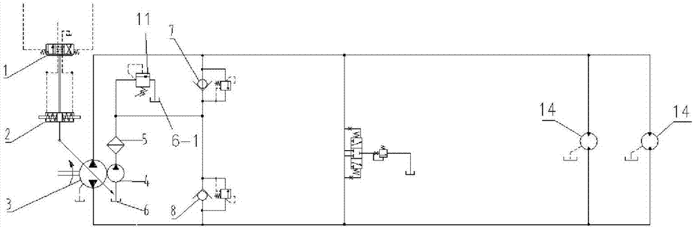
[0024] Specific implementation mode three: as image 3 As shown, the difference between this specific embodiment and specific embodiment one is: the outlet of the fine filter 5 is connected to the oil replenishment overflow valve 11, and the oil replenishment overflow valve 11 is connected to the second oil tank 6-1 connected, and there are two or more motors 14, the inlets of two or more motors 14 are connected together, the outlets of the main oil pump swash plate 3 are connected, and the outlets of two or more motors 14 are connected together, It is connected with the main oil pump swash plate 3 inlet. Other composition and connection methods are the same as those in the first embodiment.


PUM


Abstract

The invention discloses a closed hydraulic system for a heading machine and a heading machine using the system and relates the technical field of coal mine mechanical equipment. A main oil pump is a bidirectional variable pump. A first oil opening in the main oil pump communicates with a first end opening of a motor. A second oil opening in the main oil pump communicates with a second end opening of the motor. A pilot control device directly communicates with a main oil pump variable mechanism, and an inlet of a first high-pressure overflow valve and an inlet of a second high-pressure overflow valve are connected with the first oil opening of the main oil pump and the second oil opening of the main oil pump correspondingly. An outlet of the first high-pressure overflow valve and an outlet of the second high-pressure overflow valve are connected with an oil supplementing overflow valve which is connected with a second oil tank. A pilot control element is directly connected with the main oil pump variable mechanism to control the displacement of the main oil pump. The main oil pump is connected with the motor through a pipeline, and a valve throttle is arranged in the middle. Throttling losses of an opening system are avoided, energy consumption is reduced, and reversing impacts are reduced; and power losses of the device are low, the temperature rise of hydraulic oil is low, large-volume oil tank heat dissipation is not needed, only the requirement for oil supplementing needs to be met through to the oil tank volume, and equipment space and weight are saved.

Description

technical field [0001] The invention relates to a closed hydraulic system of a heading machine, which belongs to the technical field of coal mine machinery equipment. Background technique [0002] At present, the known roadheaders are all open hydraulic systems. The open system means that the hydraulic pump sucks oil from the oil tank, and supplies oil to the hydraulic cylinder or hydraulic motor through the reversing valve to drive the working mechanism. Return to the oil tank through the reversing valve. [0003] The open pump used has poor oil absorption capacity, and only a coarse filter can be used to filter between the pump and the oil tank. Impurities in the oil tank are easily mixed into the system. Fault; [0004] The power loss of the open system is large, the hydraulic oil temperature rises, a large oil tank is required, and a radiator needs to be configured, resulting in the hydraulic system taking up a lot of space and wasting energy. [0005] The reversing o...

Claims


Application Information

Patent Timeline
Patent Type & Authority Applications(China)
IPC IPC(8): F15B11/17F15B13/02F15B21/00F16B21/02F15B21/04F15B11/22
CPCF15B11/17F15B11/22F15B13/021F15B13/024F15B21/001F15B21/041F16B21/02
Inventor 丁振华韩宇刘世超
Owner 无锡华瀚能源装备科技有限公司
Why Eureka
Try Eureka