Biomass-forming fuel solid-phase low-temperature gas-phase high-temperature combustion device

A technology of biomass fuel and molding fuel, which is applied in the direction of solid fuel combustion, combustion method, fuel supply, etc., can solve the problems of ash fertilizer failure and high emission, and achieve the effects of reducing pollution, improving combustion conditions, and uniform cooling

Active Publication Date: 2017-07-04
SHANDONG UNIV OF TECH
View PDF13 Cites 10 Cited by
  • Summary
  • Abstract
  • Description
  • Claims
  • Application Information

AI Technical Summary

Problems solved by technology

[0006] The technical problem to be solved by the present invention is: to overcome the deficiencies of the prior art, and to provide a method to fundamentally solve the problems of coking, slagging, high discharge of gas-solid pollutants, and failure of ash fertilizers in burning equipment for agricultural waste such as straw, which is especially suitable for our country. Agricultural waste briquettes with high ash content combustion biomass briquettes solid-phase low-temperature, gas-phase high-temperature combustion device

Method used


Image

  • Biomass-forming fuel solid-phase low-temperature gas-phase high-temperature combustion device
  • Biomass-forming fuel solid-phase low-temperature gas-phase high-temperature combustion device
  • Biomass-forming fuel solid-phase low-temperature gas-phase high-temperature combustion device

Examples


Embodiment 1

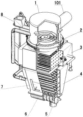
[0040] Such as figure 1 As shown: the furnace 1 is a cylinder with a closed upper end, and the bottom of the furnace 1 is a discharge port. The upper part of the furnace 1 is provided with a flame outlet 101 , and the flame outlet 101 is arranged on one side of the furnace 1 and along the tangential direction of the furnace 1 .

[0041] A feeding mechanism 8 is connected to the middle of the furnace 1, and the feeding mechanism 8 includes a feed hopper and an input auger. The input auger is set horizontally, and the discharge end of the input auger communicates with the inner cavity of the furnace 1. The hopper is a cylindrical shape with both upper and lower ends open. The hopper is arranged at the feed end of the input auger. The hopper is a cone whose cross-sectional area gradually decreases from top to bottom. The input auger is connected with a feed intake pipe, so that the input auger and the biomass fuel in the input auger can be cooled, and it can also assist the fee...

Embodiment 2

[0075] Such as Figure 12 Shown: the difference between embodiment 2 and embodiment 1 is: the smoldering pool air intake box 25 includes the smoldering pool combustion-supporting box and the smoldering pool cooling box, and the smoldering pool cooling box and the smoldering pool combustion-supporting box are set independently. Air inlet pipe 27 comprises combustion-supporting air inlet pipe 41 and cooling air inlet pipe 42, and combustion-supporting air inlet pipe 41 and cooling air inlet pipe 42 are all arranged in the smoldering pool 20, and the right end of combustion-supporting air inlet pipe 41 and the smoldering pool combustion-supporting The box is communicated, and the right end of the cooling air inlet pipe 42 is communicated with the cooling tank of the smoldering pool. The left ends of the combustion-supporting air inlet pipe 41 and the cooling air inlet pipe 42 are all communicated with the gas outlet box 28 of the smoldering pool. The combustion-supporting air in...


PUM


Abstract

The invention provides a biomass-forming fuel solid-phase low-temperature gas-phase high-temperature combustion device and belongs to the technical field of biomass combustion. The biomass-forming fuel solid-phase low-temperature gas-phase high-temperature combustion device is characterized in that a feeding opening of a smoldering region (3) communicates with a discharging opening of a hearth (1), a discharging opening of the smoldering region (3) communicates with a cooling region (4), a furnace grate (13) is arranged on the lower portion of the hearth (1), a crushing mechanism (2) for crushing materials is arranged on the furnace grate (13), the furnace grate (13) is connected with a rotating mechanism for disturbing biomass fuel so that carbon powder can fall into the smoldering region (3) to be smoldered, meanwhile the block-shaped biomass fuel is made to move to the middle of the furnace grate (13), and the crushing mechanism (2) is used for crushing the block-shaped biomass fuel into the carbon powder and then enabling the carbon powder to fall into the smoldering region (3) to be smoldered. By the adoption of the biomass forming fuel solid-phase low-temperature gas-phase high-temperature combustion device, the problems of coking, slag bonding, the high gas-solid pollutant emission and invalid ash fertilizer existing in combustion equipment for agricultural waste such as straw are solved fundamentally.

Description

technical field [0001] The utility model relates to a solid-phase low-temperature and gas-phase high-temperature combustion device for biomass briquette fuel, which belongs to the technical field of biomass combustion. Background technique [0002] With the adjustment of my country's agricultural structure and the development of rural economy, it is urgent to solve the problem of distributed small-scale heating such as drying of agricultural products and heating of agricultural facilities. For example: my country's grain drying mechanization level is 10% (the level of 80-90% in Japan and South Korea), and the loss of wet grain mildew is as high as 5% (less than 1% in developed countries). There is an urgent need to develop drying machinery and its matching small and medium-sized heating devices (generally less than 2.8MW). The heating demand of agricultural facilities (livestock and poultry houses, greenhouses, etc.) in 2 / 3 of my country's land area is also extremely urgent...

Claims


Application Information

Patent Timeline
Patent Type & Authority Applications(China)
IPC IPC(8): F23B90/06F23B40/00F23K3/00
CPCF23B40/00F23B90/06F23K3/00
Inventor 何芳张艳玲高振强杨彬彬孙鹏
Owner SHANDONG UNIV OF TECH
Why Eureka
Try Eureka