
All-pass filtering harmonic-eliminating structure and control method for intermediate-voltage power grid system

A power grid system, medium voltage technology, applied in the field of power grid, can solve the problems of large one-time investment, complex control method, insufficient filtering ability, inferior accuracy and reliability as relay protection devices, etc.

Active Publication Date: 2017-07-07
韶关市佰瑞节能科技有限公司
View PDF6 Cites 3 Cited by
  • Summary
  • Abstract
  • Description
  • Claims
  • Application Information

AI Technical Summary

Problems solved by technology

[0005] ⑴Limitations and disadvantages of existing filter compensation technology
[0006] Because the active filter (APF) and solar energy, wind power, frequency converter, SVG, etc. all adopt the current conversion technology, and its core working components are IGBT high-speed switches, so the active filter technology cannot eliminate the high Harmonic pollution caused by frequency modulated carrier; the traditional capacitor filter compensation device has a tuning point that only has the effect of filtering and eliminating harmonics corresponding to the tuning point and the left and right side frequencies, but the fact that the background harmonic spectrum of the power grid is rich. It can be considered as a continuous frequency spectrum in the time period, and the traditional capacitance filter compensation device adopts the second-order high-pass often has a large loss, and the C-type high-pass investment is large, so the compensation device generally uses series reactance to reduce the harm of harmonics to the capacitor. The capacitance current of the line is getting bigger and bigger, and the contradiction between the insufficient filtering ability and the excessive compensation of the traditional capacitor filter compensation device is becoming more and more prominent
[0007] ⑵Limitations and shortcomings of existing harmonic elimination technology
[0008] 10. The 35kV power grid generally uses traditional capacitor filter compensation devices to filter and eliminate harmonics at the tuning point and nearby harmonics. Resonant energy such as high-frequency resonance provides ground discharge channels; in addition, PT resonance elimination technology is widely used in 10 and 35kV power grids, among which PT secondary resonance elimination technology has detection blind spots for high-frequency resonance signals; PT primary resonance elimination technology is due to various When the resonant voltage of the frequency is reflected on the three-phase star contact of the primary winding of the PT, there are random changes in the magnitude of the harmonic voltage value, and it is difficult to select the frequency point for the action threshold of the nonlinear element
[0009] ⑶ Limitations and shortcomings of existing grounding technology
[0010] Resonant grounding is a grounding technology vigorously promoted by the power grid at present, but objectively there are multiple resonance points in the loop inductance and the distributed capacitance of the line change to the ground, which may easily cause the fundamental frequency current of the grounding point to be zero during tuning, and the harmonic current is too large And the problem of not being able to extinguish the arc; there is also the problem that the grounding current at the grounding point becomes smaller due to resonance compensation, resulting in difficult detection; in addition, the accuracy and reliability of the current centralized grounding line selection control device are far inferior to the relay protection device, and there is If the function of the device fails, it is difficult to confirm in advance and the function is difficult to review after repair or replacement
[0011] Small resistance grounding has been applied to a certain extent in urban power grids where cables are commonly used, but it will reduce the reliability of power supply to a certain extent; Insufficiency of complex investment control methods

Method used


Image

  • All-pass filtering harmonic-eliminating structure and control method for intermediate-voltage power grid system
  • All-pass filtering harmonic-eliminating structure and control method for intermediate-voltage power grid system
  • All-pass filtering harmonic-eliminating structure and control method for intermediate-voltage power grid system

Examples


Embodiment Construction

[0044] The present invention will be described in further detail below in conjunction with the examples and the accompanying drawings, but the embodiments of the present invention are not limited thereto.

[0045] In order to solve the defects of the prior art, the present invention integrates the common functional units of the filter compensation device, the grounding device, and the harmonic elimination device to realize full-frequency harmonic elimination. The device provides a method. The specific technical solutions and principles are introduced in detail through the following examples.

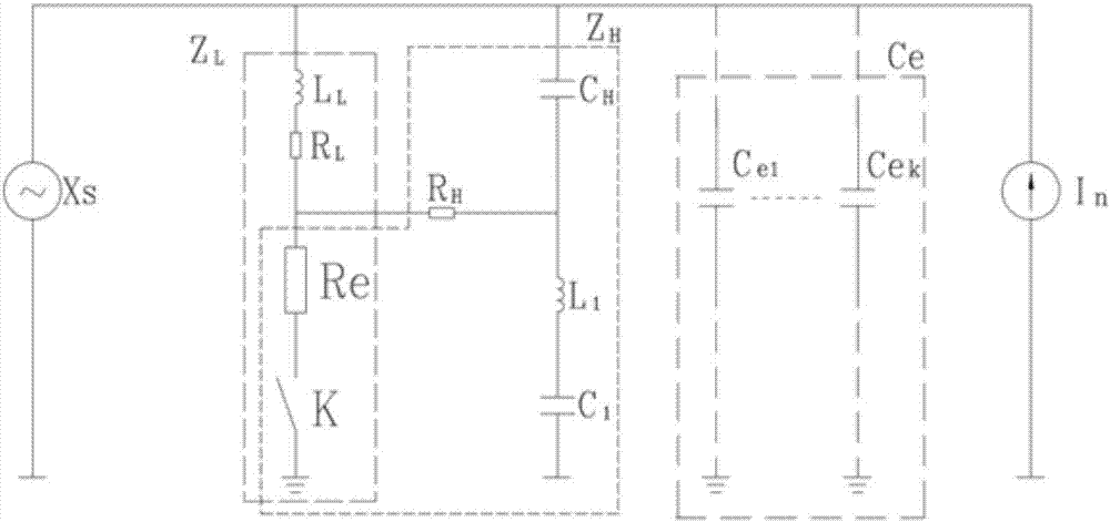
[0046] see figure 1 , which is a schematic diagram of an all-pass filter structure for a medium-voltage grid system according to the present invention.

[0047]The invention provides an all-pass filter structure for a medium-voltage grid system, including a low-pass inductance L L , low-pass resistance R L , grounding resistance Re, star point grounding switch K, high-pass capacitor ...


PUM


Abstract

The invention provides a full-pass structure, which is formed by fusing functional units of grounding equipment and compensation equipment, for the intermediate-voltage power grid system. A grounding loop of the grounding equipment serves to filter and eliminate low-frequency harmonic waves, and the reconstructed capacitive reactive compensation equipment serves to filter and eliminate other harmonic waves. The invention also provides a grounding control method in which the structure is used. Compared with the prior art, functions of filtering compensation equipment, grounding equipment, PT harmonic elimination equipment and a protective relaying device are combined, full-frequency filtering and harmonic elimination are realized, and a relay protection system realizes grounding control and grounding line-selection tripping.

Description

technical field [0001] The invention relates to the field of power grids, and in particular proposes a method for transforming existing equipment into an all-pass structure for a medium-voltage power grid system to realize full-frequency filtering and harmonic elimination, and accordingly proposes a grounding control method. Background technique [0002] The neutral point of my country's medium-voltage (10, 35kV) power grid is ungrounded. When a single-phase ground fault occurs, it is allowed to run for two hours because the three-phase symmetry of the system is not broken. However, when the line-to-ground capacitive current exceeds 10A, the arc at the grounding point cannot be automatically extinguished and a dangerous grounding overvoltage may occur. For this reason, in recent years, the technology of neutral point grounding through small resistance, resonance grounding, and fusion of resistance and automatic arc suppression coil have been developed. Composite grounding te...

Claims


Application Information

Patent Timeline
Patent Type & Authority Applications(China)
IPC IPC(8): H02J3/01H02J3/18H02J3/00H02H9/08H02H7/26
CPCH02H7/26H02H9/08H02J3/00H02J3/01H02J3/1821Y02E40/30Y02E40/40
Inventor 李清远吴疑
Owner 韶关市佰瑞节能科技有限公司
Learn More