Apparatus for concentrating ammonium sulfate slurry by using flue gas enthalpy

A technology of ammonium sulfate slurry and flue gas, which is applied in the direction of ammonium sulfate, evaporator accessories, evaporation, etc., can solve the problems of poor quality of ammonium sulfate products, restrictions on ammonia desulfurization process, high operating costs, etc., and achieve diameter reduction, The effect of saving investment and reducing the volume of flue gas

Inactive Publication Date: 2017-07-11
JIANGSU KEHANG ENVIRONMENT ENG TECH
View PDF0 Cites 4 Cited by
  • Summary
  • Abstract
  • Description
  • Claims
  • Application Information

AI Technical Summary

Problems solved by technology

Disadvantages: large investment, high operating cost, need to consume a lot of steam, and the cost of producing one ton of ammonium sulfate increases by about 200~300 yuan
[0005] The above two crystallization methods have their own advantages and disadvantages. The disadvant

Method used


Image

  • Apparatus for concentrating ammonium sulfate slurry by using flue gas enthalpy
  • Apparatus for concentrating ammonium sulfate slurry by using flue gas enthalpy

Examples


Embodiment 1

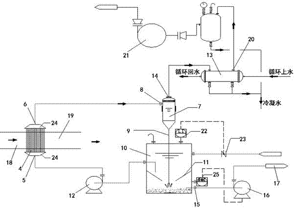
[0025] Such as figure 1 As shown, a device for concentrating ammonium sulfate slurry using flue gas heat enthalpy includes a tubular heat exchanger 4 connected to the flue of the desulfurization tower, and the bottom of the tube side of the tubular heat exchanger 4 is provided with ammonium sulfate slurry Liquid inlet 5, the tube side top of described tubular heat exchanger 4 is provided with ammonium sulfate steam outlet 6, and described ammonium sulfate steam outlet 6 links to each other with the ammonium sulfate steam inlet 8 on the buffer tank 7, and described buffer tank 7 The bottom is connected with the reflux pipe 9 that is used to export the ammonium sulfate-containing slurry, and the reflux pipe 9 stretches into the crystallization circulation tank 10 bottom, and the crystallization circulation tank 10 inwall is connected with a funnel-shaped crystallization tank ring plate 11, and the reflux The pipe 9 passes through the ring plate 11 of the crystallization tank, an...

Embodiment 2

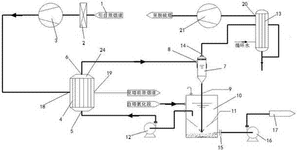
[0039] Such as figure 2 As shown, the difference between this embodiment and Embodiment 1 is only that the tubular heat exchanger 4 is not built into the flue of the desulfurization tower, but a branch flue 1 is drawn from the flue of the desulfurization tower, and the branch flue An induced draft fan A3 is arranged behind the channel 1, and the tube heat exchanger 4 is connected behind the induced draft fan A3, which is an external type. The branch flue 1 is provided with a flapper valve 2 for adjusting the flow of flue gas, and the flapper valve 2 is located in front of the induced draft fan A3. The branch flue 1 in front of the tubular heat exchanger 4 is made of carbon steel; the branch flue 1 behind the tubular heat exchanger 4 is made of carbon steel when the smoke temperature is calculated to be higher than the dew point. Steel material, when the smoke temperature is calculated to be lower than the dew point, the carbon steel lining flake material is used.


PUM


Abstract

The invention provides a device for concentrating ammonium sulfate slurry by using the heat enthalpy of flue gas, which includes a tubular heat exchanger (4) connected to the flue of the desulfurization tower, and the bottom of the tube side of the tubular heat exchanger (4) is arranged There is an ammonium sulfate slurry inlet (5), and the top of the tube side of the tubular heat exchanger (4) is provided with an ammonium sulfate steam outlet (6), and the ammonium sulfate steam outlet (6) is connected to the buffer tank (7) The ammonium sulfate steam inlet (8) on the top is connected, and the bottom of the buffer tank (7) is connected with a return pipe (9) for exporting the ammonium sulfate-containing slurry, and the return pipe (9) extends into the crystallization circulation tank (10) At the bottom, a funnel-shaped crystallization tank ring plate (11) is connected to the inner wall of the crystallization circulation tank (10), and the return pipe (9) passes through the crystallization tank ring plate (11). The invention utilizes the heat enthalpy of flue gas to evaporate and concentrate the ammonium sulfate solution, and can produce high-quality ammonium sulfate products without direct gas-liquid contact.

Description

technical field [0001] The invention relates to a device for concentrating ammonium sulfate slurry by using flue gas heat enthalpy, which belongs to the technical field of environmental protection. Background technique [0002] Among the many process routes for flue gas treatment of boilers and kilns, ammonia desulfurization has short process flow, mature process, stable operation, low cost, and small footprint. , so this process is more and more favored by production enterprises, especially enterprises that produce waste ammonia water as a by-product in the production process. [0003] At present, there are mainly two crystallization methods for ammonium sulfate produced by ammonia desulfurization. One is saturated crystallization in the tower. Using the heat enthalpy of the flue gas, the flue gas directly contacts the ammonium sulfate slurry in the desulfurization tower, and the high-temperature flue gas evaporates the water in the slurry. , reach a saturated state, the s...

Claims


Application Information

Patent Timeline
IPC IPC(8): B01D1/00B01D1/30C01C1/24
CPCB01D1/00B01D1/30C01C1/24
Inventor 刘怀平李承泉曾辉刘季平
Owner JIANGSU KEHANG ENVIRONMENT ENG TECH
Why Eureka
Try Eureka