Step recycling method and device of boiler flue gas waste heat

A cascade recovery and boiler flue gas technology, which is applied in steam engine installations, climate sustainability, sustainable manufacturing/processing, etc., can solve problems such as forced shutdown, aggravated pipeline heating surface wear, and increased flue resistance, achieving safety High performance and reduced risk of tube clogging due to dust accumulation

Inactive Publication Date: 2011-09-21
冯伟忠
View PDF10 Cites 3 Cited by
  • Summary
  • Abstract
  • Description
  • Claims
  • Application Information

AI Technical Summary

Problems solved by technology

[0005] 1. The area between the air preheater and the precipitator is a high dust content area with high fly ash content. Taking the electrostatic precipitator as an example, the dust removal efficiency is calculated according to 99.8%. , high fly ash content will aggravate the wear of the heating surface of the pipe, shorten the service life of the heat transfer pipe, and reduce the safety factor of the equipment
[0006] 2. With this arrangement, the low-temperature section of the low-pressure economizer is arranged in the high-dust area of ​​the boiler, and the risk of soot sticking due to low-temperature dew condensation in the tube row will increase greatly. Once this happens, it will cause the tube row The sticking and clogging of soot greatly increases the resistance of the flue, causing the boiler to drop the load or even force the shutdown
[0007] 3. If there is low-temperature condensation in the low-temperature section

Method used


Image

  • Step recycling method and device of boiler flue gas waste heat
  • Step recycling method and device of boiler flue gas waste heat
  • Step recycling method and device of boiler flue gas waste heat

Examples


specific Embodiment 1

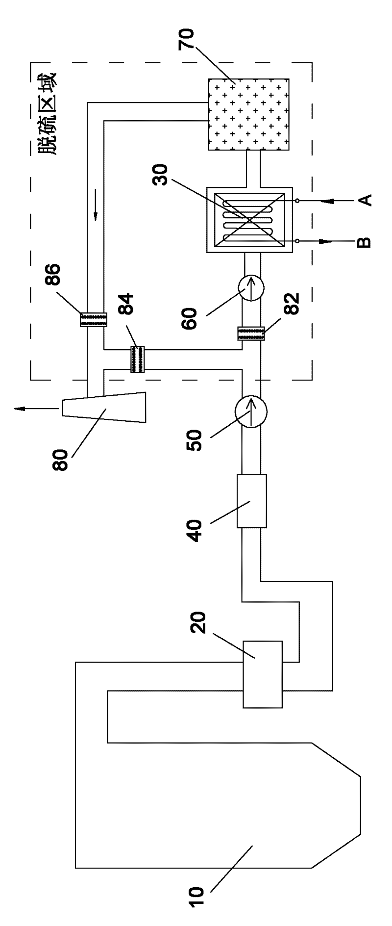
[0055] like Figure 7 As shown, the flue gas waste heat recovery device is divided into two stages and arranged in the boiler tail flue and desulfurization flue. The first-stage heat exchanger 31 is arranged between the desulfurization system booster fan 60 and the absorption tower 70, and the second-stage heat exchanger 32 is arranged between the outlet of the air preheater 20 and the inlet of the dust collector 40 in the tail flue of the boiler .

[0056] In the desulfurization area, there is also a bypass flue gas channel connected from the outlet of the induced draft fan 50 to the chimney 80, a desulfurization bypass baffle 84 is provided in the bypass flue gas channel, and an inlet baffle 82 is provided at the inlet of the booster fan 60 , the outlet of the absorption tower 70 is provided with an outlet baffle 86; when the first-stage heat exchanger 31 or other components in the desulfurization area fail, the desulfurization bypass baffle 84 is opened, the inlet baffle 8...

specific Embodiment 2

[0064] like Figure 8 As shown, with the continuous improvement of the country's requirements for environmental protection facilities, it has become a major trend in the future that the desulfurization system of the thermal power unit is not equipped with a bypass. The idea of ​​the present invention is also applicable to units that are not equipped with a desulfurization bypass.

[0065] The flue gas waste heat recovery device is also divided into two stages and arranged in the flue and the desulfurization flue at the tail of the boiler 10 . The first-stage heat exchanger 31 is arranged between the desulfurization system booster fan and the absorption tower, and the second-stage heat exchanger 32 is arranged between the outlet of the air preheater and the inlet of the dust collector in the tail flue of the boiler.

[0066] The flow of the flue gas side of the flue gas waste heat recovery device is as follows: the flue gas discharged from the boiler 10 passes through the air p...

specific Embodiment 3

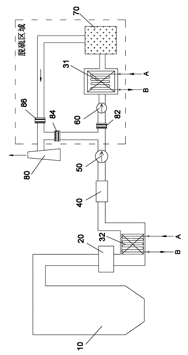
[0068] like Figure 9 As shown, the flue gas waste heat recovery device is divided into three stages and arranged in the boiler tail flue and desulfurization flue. The first-stage heat exchanger 31 is arranged between the desulfurization system booster fan 60 and the absorption tower 70, and the second-stage heat exchanger 32 is arranged between the outlet of the air preheater 20 and the inlet of the dust collector 40 in the tail flue of the boiler , an intermediate stage heat exchanger 33 is added, arranged in the flue between the outlet of the induced draft fan 50 and the inlet of the booster fan 60 .

[0069] The flow of the flue gas side in the flue gas waste heat recovery device is as follows: the flue gas discharged from the boiler 10 passes through the air preheater 20, enters the second-stage heat exchanger 32 to release part of the heat, and then passes through the dust collector 40 and the induced draft fan 50 to perform work , the temperature of the flue gas is inc...


PUM


Abstract

The invention discloses a step recycling method of boiler flue gas waste heat. The method is used for a steam turbine generator unit, and comprises temperature rise generated by multistage heat exchange and work of parts in a flue gas passage in an energy step reclamation mode. The invention also discloses a boiler flue gas waste heat recycling device for implementing the method. The device comprises multistage heat exchangers, wherein the flue gas sides of the heat exchangers are arranged at different positions in the flue gas passage, and the water sides of the heat exchangers are connected with a low-pressure water supply system of the steam turbine generator unit. According to the method and the device, work energy of equipment such as a draught fan, a booster fan and the like in a flue gas system can be optimally utilized and absorbed, the arrangement is more flexible, and the conventional equipment and the conventional system are affected and changed little.

Description

technical field [0001] The invention relates to a method and a device for cascade recovery and utilization of waste heat of boiler flue gas, which are used for steam turbine generator sets. Background technique [0002] The traditional low-pressure economizer is an energy-saving measure that utilizes waste heat from boiler exhaust. like figure 1 As shown, the low-pressure economizer is a heat exchanger 30, the flue gas side is installed in the tail flue of the boiler 10, and its water side is connected to the low-pressure water supply system part (A, B) of the steam turbine, and the low-pressure water supply is in the low-pressure economizer It absorbs the heat of the exhaust smoke, reduces the temperature of the exhaust smoke, and returns to the low-pressure water supply system of the steam turbine after being heated and raised in temperature to replace part of the low-pressure heater. It is an integral part of the thermal system of the steam turbine. The low-pressure eco...

Claims


Application Information

Patent Timeline
IPC IPC(8): F01K27/02F01D15/10
CPCY02P80/15
Inventor 冯伟忠
Owner 冯伟忠
Why Eureka
Try Eureka