
Coal-fired boiler smoke purifying and waste heat recovery treating system and method

A coal-fired boiler and waste heat recovery technology, applied in the direction of combustion method, combustion product treatment, greenhouse gas reduction, etc., can solve the problems of poor effect, reduced desulfurization efficiency, environmental impact, etc., to achieve temperature reduction, occupy less space, Energy Saving Effect

Pending Publication Date: 2017-07-11
烟台盛海源节能科技有限公司
View PDF5 Cites 9 Cited by
  • Summary
  • Abstract
  • Description
  • Claims
  • Application Information

AI Technical Summary

Problems solved by technology

[0005] However, in this scheme, the flue gas from the coal-fired boiler directly enters the air preheater for heat exchange, and then enters the desulfurization tower for treatment. There is no denitrification, dust removal and other treatment procedures, which will reduce the desulfurization efficiency and effect. On the other hand More importantly, the flue gas after desulfurization treatment is directly discharged through the chimney, because the desulfurization efficiency is closely related to the temperature of the flue gas, and there are often strict requirements on the flue gas entering the desulfurization tower, so that the desulfurization efficiency and energy utilization The desulfurization and purification flue gas treated in this way often has a lower temperature, still has a lot of smoke and dust, and contains a lot of water, and it will have a great impact on the environment if it is directly discharged into the atmosphere

Method used


Image

  • Coal-fired boiler smoke purifying and waste heat recovery treating system and method

Examples


Embodiment Construction

[0037] In order to make the object, technical solution and advantages of the present invention clearer, the present invention will be further described in detail below in conjunction with the accompanying drawings and embodiments. It should be understood that the specific embodiments described here are only used to explain the present invention, not to limit the present invention.

[0038] In addition, the technical features involved in the various embodiments of the present invention described below can be combined with each other as long as they do not constitute a conflict with each other.

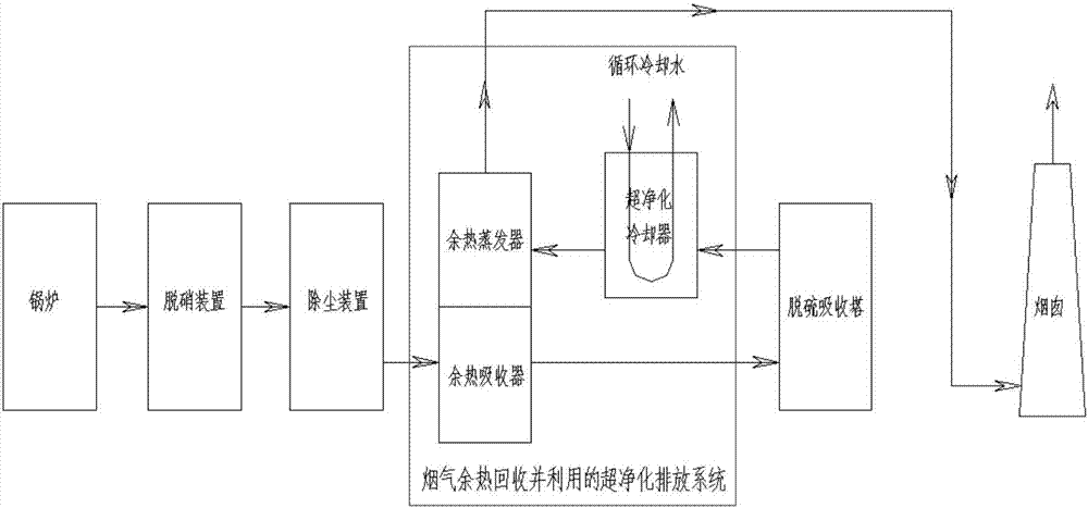
[0039] figure 1 It is a structural schematic diagram of a coal-fired boiler flue gas purification and waste heat recovery treatment system according to an embodiment of the present invention.

[0040] Such as figure 1 As shown, the coal-fired boiler flue gas purification and waste heat utilization treatment system according to the embodiment of the present invention is installed on th...


PUM


Abstract

The invention discloses a coal-fired boiler smoke purifying and waste heat recovery treating system. The coal-fired boiler smoke purifying and waste heat recovery treating system comprises a waste heat exchanger, a smoke super purifier, a washing and spraying system and a smoke super purification cooler, wherein the waste heat exchanger comprises a waste heat absorber and a waste heat evaporator, the waste heat absorber is arranged on a desulfurizing tower smoke inlet pipeline, the smoke super purifier is arranged on a desulfurizing tower smoke outlet pipeline, smoke subjected to desulfurizing treatment enters the smoke super purifier to be condensed, and the washing and spraying system is used for spraying and washing separated-out harmful smoke; and the waste heat evaporator is arranged on a smoke pipeline between the smoke super purifier and a chimney, connected with the waste heat absorber and used for smoke for waste heat heating, and after the temperature of the smoke is raised, the smoke is exhausted through the chimney. The invention further discloses a corresponding treating method. By means of the system and method, waste heat in the high-temperature smoke can be effectively extracted, and the system utilizing waste heat recycled through the high temperature for reheating and discharging the smoke achieves the purposes of comprehensively saving energy and carrying out discharging in an environmental-friendly manner.

Description

technical field [0001] The invention relates to the field of coal-fired boiler flue gas treatment, in particular to a coal-fired boiler flue gas purification and waste heat recovery treatment system and method. Background technique [0002] my country is a big coal-burning country, and coal consumption accounts for more than 70% of the total primary energy. Coal combustion emits a large amount of air pollutants at the same time. According to statistics, coal burning SO 2 , NOx, and particulate matter emissions accounted for 90%, 67%, and 70% of the country's total emissions, respectively. Among these pollutants, SO2 and NOx are acidic, which combine with particulate matter and settle to form acid rain. In 2010, the area of ​​acid rain in my country was 1.4 million square kilometers, accounting for 14% of the country's land area, and serious regional complex pollution occurred in some areas. Following the Eleventh Five-Year Plan, coal-fired SO 2 As a binding indicator of s...

Claims


Application Information

Patent Timeline
IPC IPC(8): F23J15/02F23J15/06F23J15/08
CPCF23J15/006F23J15/02F23J15/06F23J15/08F23J2215/20F23J2215/10F23J2900/15081F23J2900/13001Y02E20/30
Inventor 杨生贵王志强赵伟玲宫婷婷崔迪
Owner 烟台盛海源节能科技有限公司
Learn More