Variable-gradient fractal lattice sandwiched reinforcement phase change heat sink

A technology for enhancing phase and phase change heat, which is applied in the short-term or periodic heat dissipation control and the instantaneous field of electronic equipment, and can solve the problems of low utilization rate of enhanced heat transfer materials, limitation of comprehensive heat transfer efficiency, and high utilization rate of enhanced heat transfer materials. , to achieve the effect of improving the comprehensive heat transfer efficiency, improving the comprehensive heat transfer efficiency, and high comprehensive heat transfer efficiency

Active Publication Date: 2017-07-11
10TH RES INST OF CETC
View PDF12 Cites 42 Cited by
  • Summary
  • Abstract
  • Description
  • Claims
  • Application Information

AI Technical Summary

Problems solved by technology

[0007] All the enhanced heat transfer structures (fins, fins, wire mesh, foam or mesh) in the above technical solutions are evenly distributed in the heat sink package, and have the same specific surface area per unit volume (the surface area of ​​the enhanced heat transfer structure per unit volume ), so as to have the same heat transfer and heat dissipation heat exchange capacity, close to image 3 The utilization rate of the enhanced heat transfer material shown in the thermal diffusion bottom plate 7 is high, and the utilization rate of the enhanced heat transfer material far away from the thermal diffusion bottom plate 7) is low, and the heat cannot be uniformly and efficiently conducted to all phases in the phase change heat sink during the working process. Among the phase change materials, the phase change of phase change materials at different positions has obvious time difference, so the improvement of its comprehensive heat transfer efficiency is greatly limited.

Method used


Image

  • Variable-gradient fractal lattice sandwiched reinforcement phase change heat sink
  • Variable-gradient fractal lattice sandwiched reinforcement phase change heat sink
  • Variable-gradient fractal lattice sandwiched reinforcement phase change heat sink

Examples


Embodiment 1

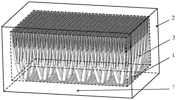
[0029] According to the heat dissipation performance index requirements of the phase change heat sink and the allowable size and weight, the external dimensions, inner cavity size, and the thickness of the thermal diffusion bottom plate 7 and the surrounding frame and cover plate of the phase change heat sink are determined by calculation. The phase change heat sink in this embodiment The overall size of the heat sink is 38mm (length) × 26mm (width) × 19mm (height), the inner cavity size is 36mm (length) × 24mm (width) × 15mm (height), the thickness of the thermal diffusion bottom plate (7) is 3mm, and the surrounding And the wall thickness of the top cover plate is 1mm, and 24 variable gradient fractal lattice sandwich structure sample units are evenly distributed on the inner surface;

Embodiment 2

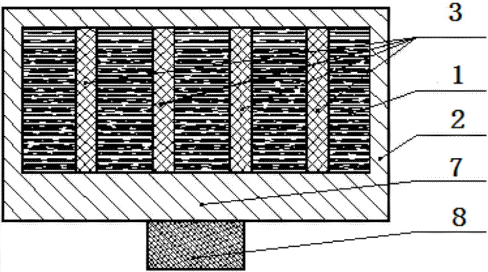
[0031] According to the heat dissipation performance index requirements of the phase change heat sink, determine the proportion of strengthening materials and phase change materials in the phase change heat sink, and determine the cross-sectional area of ​​the enhanced heat transfer structure 3 through calculation. The calculation formula is: cross-sectional area of ​​the enhanced heat transfer structure = phase Cross-sectional area of ​​variable heat sink × proportion of strengthening material. According to calculations in this example, the proportion of strengthening materials is 1 / 9 (about 11%), and the proportion of phase change materials is 8 / 9 (about 89%). Therefore, the cross-sectional area of ​​the enhanced heat transfer structure is 96mm 2 ;

Embodiment 3

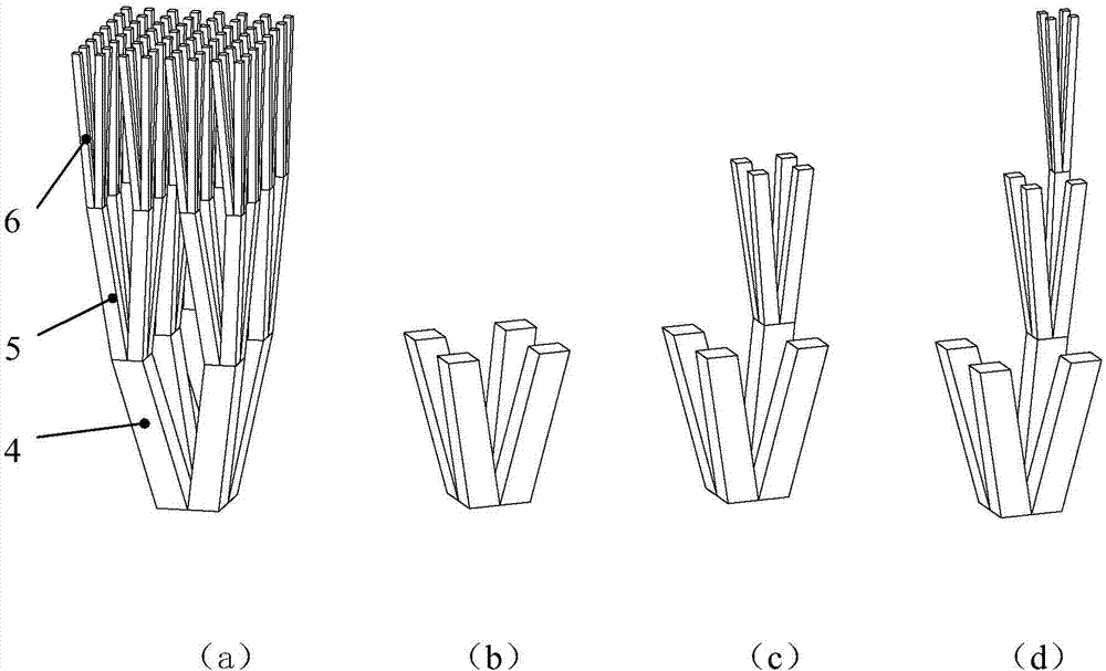
[0033] The graded gradient is determined according to the thickness of the phase change heat sink, which can be divided into several levels. In this embodiment, the number of graded gradients is determined to be 3, and the height of each gradient is 5mm;

[0034] The layout, shape, and size of the first-stage enhanced heat transfer structure 4 are determined according to the distribution law of the heat source 8, the filling rate of the reinforced material, and the number of graded gradients. In this embodiment, the first-stage enhanced heat transfer structure is determined to be on the thermal diffusion bottom plate 7 by 6mm× The spacing of 6mm is evenly distributed, the cross-sectional shape is square, and the size is 2mm×2mm;

[0035] Each level of enhanced heat transfer structure can choose the fractal method according to the shape and size of the first-level enhanced heat transfer structure and the number of classifications. In this embodiment, since the cross-sectional sh...


PUM


Abstract

The invention discloses a variable-gradient fractal lattice sandwiched reinforcement phase change heat sink and aims to provide an efficient phase change heat sink which is high in heat exchange efficiency, has certain universality and can be developed in a serialization mode. The variable-gradient fractal lattice sandwiched reinforcement phase change heat sink is realized according to the following technical scheme: reinforcement heat transfer structures are distributed in a phase change heat sink shell in an array; each variable-gradient fractal lattice sandwiched unit takes a variable-gradient V structure as a first-stage reinforcement heat transfer structure (4) according to the heat transfer and heat exchange characteristics of the phase change heat sink; on this basis, at variable-gradient V-shaped ends of the first-stage reinforcement heat transfer structures, the variable-gradient V structures in the same shape are gradually increased to form multiple stages of reinforcement heat transfer structures, and the specific surface areas of the multiple stages of reinforcement heat transfer structures are multiplied in sequence; the first-stage reinforcement heat transfer structures can transfer heat to an area far away from a heat radiation bottom plate rapidly in a reinforcement mode, and the second-stage reinforcement heat transfer structures (5) and the third-stage reinforcement heat transfer structures can transfer heat to phase change material far away from the heat radiation bottom plate rapidly to complete heat exchange.

Description

technical field [0001] The invention relates to the technical field of thermal control of electronic equipment, and is mainly used for instantaneous, short-term or periodic heat dissipation control of electronic equipment in the fields of aviation, aerospace, communication, etc., and aims to improve the comprehensive heat exchange efficiency of phase change heat sinks. Background technique [0002] As the power of electronic components increases, thermal control design plays a very important role in ensuring the normal operation of electronic components. Electronic equipment is faced with many restrictions in the work, such as very harsh working environment, confined space, unable to supply air and liquid cooling, volume and weight restrictions, insufficient heat sink capacity, external pneumatic heating and other harsh conditions, especially when working in elastic The electronic equipment in the middle and end of the loading platform itself faces a higher initial temperatu...

Claims


Application Information

Patent Timeline
Patent Type & Authority Applications(China)
IPC IPC(8): F28D20/02H01L23/427
CPCF28D20/021H01L23/427Y02E60/14
Inventor 熊长武严宏胡家渝周晓东
Owner 10TH RES INST OF CETC
Why Eureka
Try Eureka