Microwave differential gain-based coherent Doppler wind lidar

A technology of Doppler wind measurement and differential gain, which is applied in the direction of electromagnetic wave reradiation, radio wave measurement system, measurement device, etc., can solve the problems of high cost, limit the development of Doppler wind measurement lidar, etc., and reduce noise Interference, increase data processing speed, reduce the effect of calculation

Active Publication Date: 2017-07-11
夏海云
View PDF4 Cites 23 Cited by
  • Summary
  • Abstract
  • Description
  • Claims
  • Application Information

AI Technical Summary

Problems solved by technology

Although it is now possible to use DSP or FPGA to achieve real-time processing of such high-speed signals, the high cost and the higher requirements for real-time signal processing speed with the improvement of distance resolution have limited the coherent Doppler wind measurement. Development of lidar

Method used


Image

  • Microwave differential gain-based coherent Doppler wind lidar
  • Microwave differential gain-based coherent Doppler wind lidar
  • Microwave differential gain-based coherent Doppler wind lidar

Examples


Embodiment 1

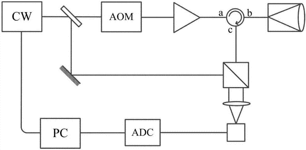
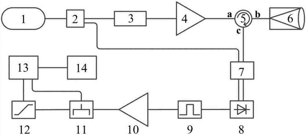
[0043] figure 2 The structural block diagram of the coherent Doppler wind lidar based on the microwave differential gain provided by the present invention, such as figure 2 As shown, the coherent Doppler wind lidar based on microwave differential gain includes:

[0044] Continuous wave laser 1, fiber beam splitter 2, optical modulator 3, laser amplifier 4, fiber optic circulator 5, transceiver telescope 6, mixer 7, photodetector 8, bandpass filter 9, preamplifier 10, Power divider 11, pre-emphasis filter 12, multi-channel acquisition card 13 and digital signal processing module 14;

[0045] The continuous wave laser 1 is used to output continuous light as seed light. In an optional embodiment, the continuous wave laser is a fiber laser, and the fiber laser has the advantages of small size and light weight.

[0046] The output end of the continuous wave laser 1 is connected to the optical entrance of the optical fiber splitter 2, and the optical fiber splitter 2 divides th...

Embodiment 2

[0093] Such as Figure 5 As shown, the present invention provides a coherent Doppler wind lidar based on microwave differential gain, comprising: a continuous wave laser 1, a beam splitter, an optical modulator 3, a laser amplifier 4, a circulator, a transceiver telescope 6, Mixer 7, photodetector 8, bandpass filter 9, preamplifier 10, power divider 11, pre-emphasis filter 12, multi-channel acquisition card 13 and digital signal processing module 14; Wherein,

[0094] The optical signal output by the continuous wave laser 1 is divided into signal light and local oscillator light after being passed through the beam splitter. After the signal light is input to the optical modulator 3 for modulation, it is input to the laser amplifier 4, and the laser amplifier 4 amplifies the input optical signal and outputs it to the The input end of the circulator, the transceiver end of the circulator is connected to the telescope 6, and the optical signal output from the output end of the op...


PUM


Abstract

The invention discloses a microwave differential gain-based coherent Doppler wind lidar. According to the technical scheme of the invention, a balanced detector is connected with a bandpass filter, so that invalid signals, away from the Doppler frequency shift, are filtered and eliminated. A pre-amplifier is adopted to amplify an electrical signal outputted by the detector. Meanwhile, a power divider is adopted to divide amplified electrical signal into a monitoring channel and a detection signal. The detection signal is filtered by a pre-emphasis filter. The frequency-domain change of the detection signal is converted to the intensity change of the signal. Through the comparison with the monitoring channel and the transmittance curve of the pre-emphasis filter, the Doppler shift information is obtained. The interference of invalid echo signals is reduced. By adopting the pre-emphasis filter, echo signals are subjected to frequency discrimination, so that the computation amount of signal processing is reduced. The sensitivity and the signal-to-noise ratio of the system are improved. The coherent Doppler wind lidar is higher in resolution distance.

Description

technical field [0001] The invention relates to the technical field of laser radar, in particular to a coherent Doppler wind measuring laser radar based on microwave differential gain. Background technique [0002] Accurate atmospheric wind field measurement is of great significance to the detection of atmospheric pollution, the acquisition of military environmental intelligence, the improvement of aerospace safety, the improvement of weather forecast accuracy, and the improvement of climate models. Observations of atmospheric properties and weather conditions have been made using lidar for more than 50 years, since Fiocco and Smullin invented the first lidar. Thanks to the development of optical fiber communication technology, the all-fiber laser radar technology based on the 1550nm communication band has developed rapidly in recent years. Japan's Mitsubishi Electromechanical Co., Ltd. reported the world's first 1.5μm coherent wind lidar. The French company LEOSPHERE prod...

Claims


Application Information

Patent Timeline
Patent Type & Authority Applications(China)
IPC IPC(8): G01S17/95
CPCG01S17/95Y02A90/10
Inventor 张仁俊赵自豪
Owner 夏海云
Why Eureka
Try Eureka