Liquid conveying pipe for construction engineering
A technology for conveying pipelines and construction projects. It is used in pipeline protection and protection of pipelines and pipes through thermal insulation. It can solve problems such as pipeline damage, low tensile strength, and no aging resistance, and achieve improved structural strength and long service life. , good thermal insulation effect
- Summary
- Abstract
- Description
- Claims
- Application Information
AI Technical Summary
Problems solved by technology
Method used
Image
Examples
Embodiment 1
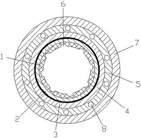
[0018] Such as figure 1 As shown, a liquid delivery pipeline for a construction project includes a ceramic inner layer 1, an insulation layer 2, an aluminum foil layer 3, an airgel layer 4 and a glass wool layer 5, and the ceramic inner layer 1, the insulation layer 2, and the aluminum foil layer 3. The airgel layer 4 and the glass wool layer 5 are arranged sequentially from the inside to the outside, the heat insulation layer 2 is glued to the ceramic inner layer 1, and a groove 6 is arranged inside the ceramic inner layer 1, and the groove 6 It is arranged in a spiral shape, a steel sleeve 7 is arranged on the outside of the glass wool layer 5, a reinforcing rib 8 is arranged inside the glass wool layer 5, and more than one reinforcing rib 8 is provided, and the reinforcing rib 8 is in a circular array distributed. The steel casing 7 is a stainless steel casing. The thickness of the insulation layer 2 is greater than 1cm. The thickness of the airgel layer 4 is equal to th...
Embodiment 2
[0024] Such as figure 1 As shown, a liquid delivery pipeline for a construction project includes a ceramic inner layer 1, an insulation layer 2, an aluminum foil layer 3, an airgel layer 4 and a glass wool layer 5, and the ceramic inner layer 1, the insulation layer 2, and the aluminum foil layer 3. The airgel layer 4 and the glass wool layer 5 are arranged sequentially from the inside to the outside, the heat insulation layer 2 is glued to the ceramic inner layer 1, and a groove 6 is arranged inside the ceramic inner layer 1, and the groove 6 It is arranged in a spiral shape, a steel sleeve 7 is arranged on the outside of the glass wool layer 5, a reinforcing rib 8 is arranged inside the glass wool layer 5, and more than one reinforcing rib 8 is provided, and the reinforcing rib 8 is in a circular array distributed. The steel casing 7 is a stainless steel casing. The thickness of the insulation layer 2 is greater than 1cm. The thickness of the airgel layer 4 is equal to th...
Embodiment 3
[0030] Such as figure 1As shown, a liquid delivery pipeline for a construction project includes a ceramic inner layer 1, an insulation layer 2, an aluminum foil layer 3, an airgel layer 4 and a glass wool layer 5, and the ceramic inner layer 1, the insulation layer 2, and the aluminum foil layer 3. The airgel layer 4 and the glass wool layer 5 are arranged sequentially from the inside to the outside, the heat insulation layer 2 is glued to the ceramic inner layer 1, and a groove 6 is arranged inside the ceramic inner layer 1, and the groove 6 It is arranged in a spiral shape, a steel sleeve 7 is arranged on the outside of the glass wool layer 5, a reinforcing rib 8 is arranged inside the glass wool layer 5, and more than one reinforcing rib 8 is provided, and the reinforcing rib 8 is in a circular array distributed. The steel casing 7 is a stainless steel casing. The thickness of the insulation layer 2 is greater than 1 cm. The thickness of the airgel layer 4 is equal to th...
PUM
| Property | Measurement | Unit |
|---|---|---|
| thickness | aaaaa | aaaaa |
| thickness | aaaaa | aaaaa |
Abstract
Description
Claims
Application Information
 - R&D
- Intellectual Property
- Life Sciences
- Materials
- Tech Scout
- Unparalleled Data Quality
- Higher Quality Content
- 60% Fewer Hallucinations
Browse by: Latest US Patents, China's latest patents, Technical Efficacy Thesaurus, Application Domain, Technology Topic, Popular Technical Reports.
© 2025 PatSnap. All rights reserved.Legal|Privacy policy|Modern Slavery Act Transparency Statement|Sitemap|About US| Contact US: help@patsnap.com


