Built-in very-high-frequency partial discharge detection device and method

A technology of partial discharge detection and very high frequency, which is applied in the field of high voltage electricity, can solve the problems of inability to realize real-time online monitoring of cable faults in time, inability to support signal acquisition, and non-fixed installation, etc., so as to improve accuracy and optimize installation location , the effect of eliminating interference

Pending Publication Date: 2017-07-14
ZHEJIANG TUWEI ELECTRICITY TECH CO LTD
View PDF7 Cites 12 Cited by
  • Summary
  • Abstract
  • Description
  • Claims
  • Application Information

AI Technical Summary

Problems solved by technology

Problems with this device: the CT ring cannot support signal acquisition at such a high frequency as 300MHz~3GHz; the device is not fixedly installed, and only conducts signal acquisition and detection through patrol inspection. This portable detection device cannot realize real-time online monitoring and timely reminder of cable faults

Method used


Image

  • Built-in very-high-frequency partial discharge detection device and method
  • Built-in very-high-frequency partial discharge detection device and method

Examples


Embodiment 1

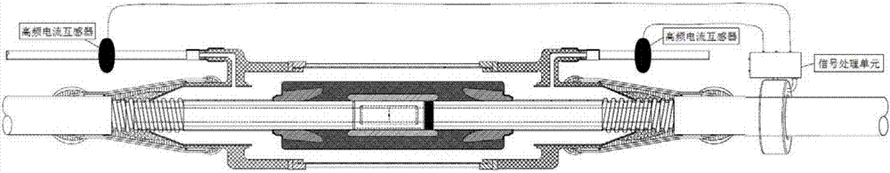
[0032] In the prior art, the cable joint is usually a high-incidence area of ​​partial discharge, which is the weakest link that affects the overall cable work; the traditional HFCT method for partial discharge detection is high-frequency signal detection. Such as figure 1 As shown in the schematic diagram of the traditional cable partial discharge signal detection device, the traditional partial discharge detection device, the high-frequency current transformer is placed on the grounding cable, and the frequency supported by the HFCT is 1M to 20M. In the prior art, there is a certain distance between the cable joint and the grounding cable outside the cable, usually more than 1 meter, and the partial discharge signal is attenuated into a high-frequency signal (between 5 and 15M) due to the inductive effect of the grounding cable of the cable. It is meaningless to use very high frequency detection; since the frequency response of HFCT current transformer is between 1 and 20M, it...

Embodiment 2

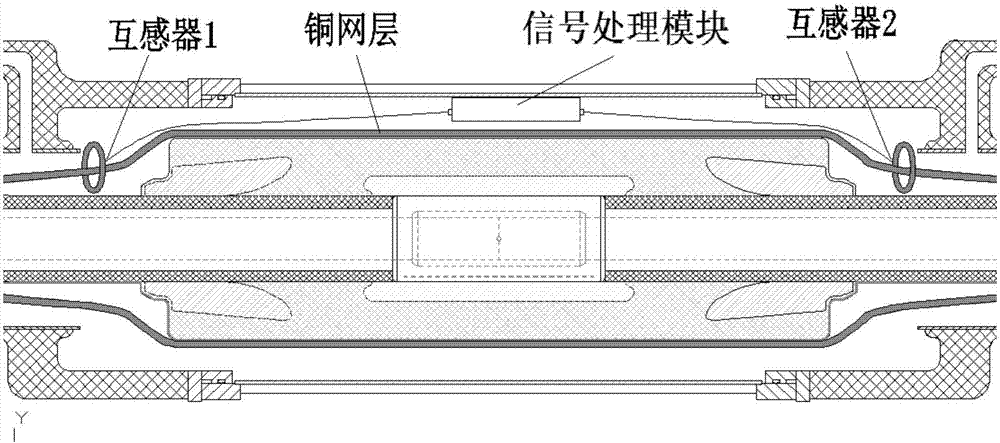
[0058] A built-in very high frequency (VHF) partial discharge detection device, the device includes a VHF current transformer, a signal acquisition module, and a signal processing module, and the VHF current transformer and signal acquisition module are installed inside the copper shell of the cable joint And through the signal line, it is connected with the signal processing module placed outside the copper shell of the cable joint.

[0059] In the built-in VHF partial discharge detection device described in the embodiment of the present invention, the VHF current transformer is a VHF current transformer made of nickel-zinc ferrite. The VHF current transformer can also be a VHF current transformer based on the Rogowski coil method. The frequency response of the VHF current transformer is 10M to 50M.

[0060] In the built-in very high frequency (VHF) partial discharge detection device described in the embodiment of the present invention, the sampling rate of the signal acquis...


PUM


Abstract

The invention relates to a built-in very-high-frequency partial discharge detection device and method. The built-in very-high-frequency partial discharge detection device comprises a very-high-frequency current transformer, a signal acquisition module and a signal processing module. According to the technical scheme of the invention, the installation position of a current transformer (CT) ring is optimized through optimizing an HFCT (High-Frequency Current Transducer) into a VHFCT (Very-High-Frequency Current Transducer), and the CT ring is installed inside a cable joint; and a copper mesh wound outside a semiconductor layer is enabled to directly penetrate through the CT ring and is then connected with a cable armoring grounding cable. Measurement is performed at a partial discharge signal generating point in situ, so that very-high-frequency characteristics of partial discharge are ensured, and the accuracy of cable partial discharge detection is enabled to be greatly improved.

Description

technical field [0001] The invention relates to the technical field of high voltage electricity, in particular to a built-in very high frequency (VHF) partial discharge detection device and method. Background technique [0002] The partial discharge of high-voltage XLPE cables is the main factor causing high-voltage cable accidents, and has been widely concerned for many years. The reason is mainly due to the defects in the insulating parts of the cables, which generate partial micro discharges. The discharge process accelerates the deterioration of the insulation performance of XLPE cables, which eventually leads to cable breakdown. How to measure the early partial discharge of cables is of great significance to the prevention of cable accidents. On the other hand, since the electric field stress of the middle joint of the power cable is relatively concentrated, it is the weak link of the power cable insulation and is more prone to insulation failure. According to statis...

Claims


Application Information

Patent Timeline
Patent Type & Authority Applications(China)
IPC IPC(8): G01R31/12
CPCG01R31/1272
Inventor 王玮臧磊朱祖华
Owner ZHEJIANG TUWEI ELECTRICITY TECH CO LTD
Why Eureka
Try Eureka