
A cryogenic liquid storage tank with porous media

A porous medium and cryogenic liquid technology, applied in gas/liquid distribution and storage, fixed-capacity gas storage tanks, outer walls of container structures, etc., can solve the problem of increased heat leakage of storage tanks, increase of storage tanks, reduction of storage tank capacity, etc. problem, to achieve the effect of large contact thermal resistance, simple implementation method, and slow down the formation rate

Active Publication Date: 2019-05-07
ZHEJIANG UNIV
View PDF4 Cites 0 Cited by
  • Summary
  • Abstract
  • Description
  • Claims
  • Application Information

AI Technical Summary

Problems solved by technology

However, on the one hand, the fins will increase the extra mass of the storage tank and reduce the capacity of the storage tank; on the other hand, it will also increase the heat leakage between the storage tank and the environment, which has obvious disadvantages

Method used


Image

  • A cryogenic liquid storage tank with porous media
  • A cryogenic liquid storage tank with porous media
  • A cryogenic liquid storage tank with porous media

Examples


Embodiment 1

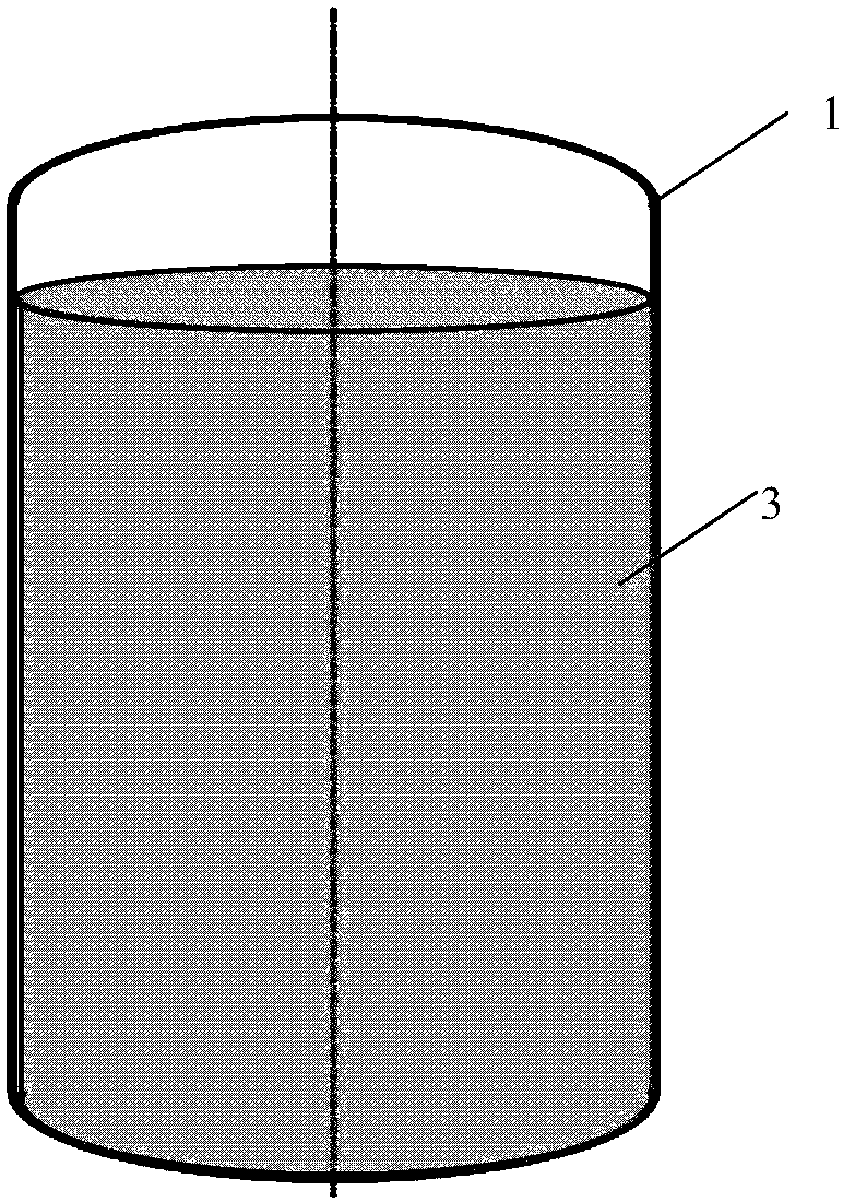
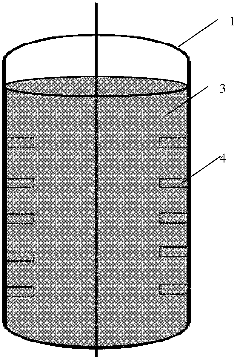
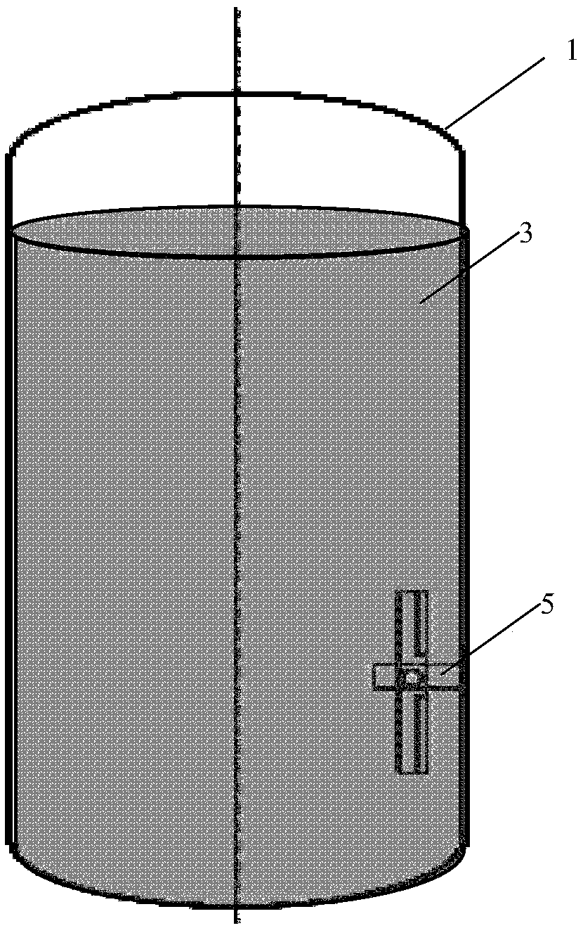
[0030] like Figure 1~3 As shown, the cryogenic liquid storage tank in the prior art has a ribbed structure and a structure with a built-in rotating agitator to reduce the temperature of the cryogenic liquid storage tank and eliminate thermal stratification of the cryogenic liquid.

[0031] figure 1 Among them, the cryogenic liquid storage tank includes a cryogenic storage tank body 1 and a filled cryogenic liquid 3 . figure 2 Among them, the tank body 1 of the cryogenic storage tank is provided with fins 4 . image 3 Among them, a rotating agitator 5 is arranged in the tank body 1 of the cryogenic storage tank.

[0032] like Figure 4 As shown, the cryogenic liquid storage tank of this embodiment includes: a cryogenic storage tank body 1 , a filled cryogenic liquid 3 and a porous medium filler 2 .

[0033] In this embodiment, the cryogenic storage tank body 1 is composed of an upper and lower elliptical head and a cylindrical shell, and the porous medium filler 2 is only...

Embodiment 2

[0037] This embodiment is the same as Embodiment 1 except for the structure of the porous media filler 2 .

[0038] like Figure 5 and 6 As shown, the porous medium filler 2 of this embodiment adopts a metal copper wire mesh with a diameter of 0.1 mm, 20 meshes, and a porosity of 0.94, and is arranged on the inner wall of the low-temperature storage tank body 1 in a ring.

[0039] The number of porous media filler 2 wall-adhering annular structures is 100, and the ratio of the total thickness of the wire mesh to the diameter of the low-temperature storage tank is 1:25.

Embodiment 3

[0041] This embodiment is the same as Embodiment 1 except for the structure of the porous media filler 2 .

[0042] like Figure 7 As shown, the porous medium filler 2 of this embodiment adopts a commercially available copper wire mesh with a diameter of 0.1 mm, 20 meshes, and a porosity of 0.94. The metal copper wire mesh is evenly filled with cryogenic liquid3.


PUM


Abstract

The invention discloses a cryogenic liquid storage tank with a porous medium. The cryogenic liquid storage tank comprises a cryogenic liquid storage tank body used for storing cryogenic liquid, and porous medium filler covering the cryogenic liquid is arranged inside the cryogenic liquid storage tank body. According to the cryogenic liquid storage tank with the porous medium, the thermal contact resistance between the porous medium and the wall surface is large, and the influence of environment heat leakage is reduced; the heat transfer of the liquid in the tank is accelerated, and the formation speed of the thermal stratification is slowed down; and the overall weight is small, and the influence on the capacity is small.

Description

technical field [0001] The invention relates to the technical field of cryogenic liquid storage, in particular to a cryogenic liquid storage tank with a porous medium. Background technique [0002] During the tank storage and transportation of cryogenic liquids and cryogenic fuels, due to the inevitable environmental heat leakage, the cryogenic liquids (liquid helium, liquid hydrogen, liquid neon, liquid nitrogen, liquid oxygen, liquefied Natural gas, etc.) is heated first, and the temperature rises. The hot fluid flows upward under the action of the buoyancy force, resulting in uneven temperature distribution of the fluid in the tank and thermal stratification. At the hot fluid part close to the gas-liquid phase interface, the vaporization of the liquid at the interface intensifies, and the pressure inside the tank increases, causing a major safety hazard in the tank. Especially for the ground storage and transportation of low-temperature fuel, as well as fuel storage dur...

Claims


Application Information

Patent Timeline
Patent Type & Authority Patents(China)
IPC IPC(8): F17C3/06
CPCF17C3/06F17C2203/0304F17C2203/0345
Inventor 植晓琴周霞邱利民
Owner ZHEJIANG UNIV
Learn More