Self-powered liquid pitometer
A tachometer, self-powered technology, applied in fluid velocity measurement, velocity/acceleration/shock measurement, electric vehicles, etc., can solve problems such as pressure drop of turbine flowmeter, and achieve the effect of high integration
- Summary
- Abstract
- Description
- Claims
- Application Information
AI Technical Summary
Problems solved by technology
Method used
Image
Examples
Embodiment 1
[0037] The present invention designs a self-powered liquid flow meter, and the technical solution of the present invention is further described below in conjunction with the accompanying drawings and specific examples:
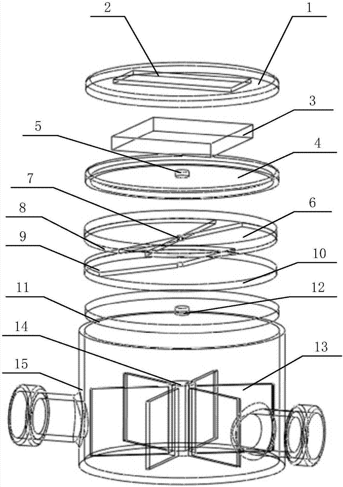
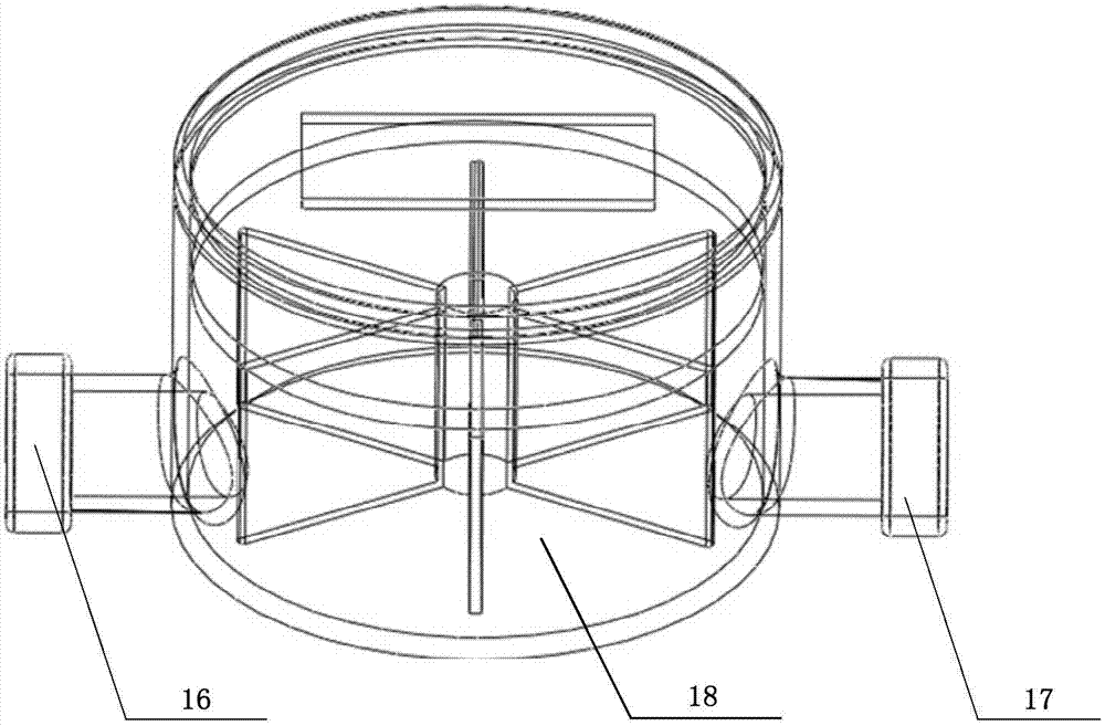
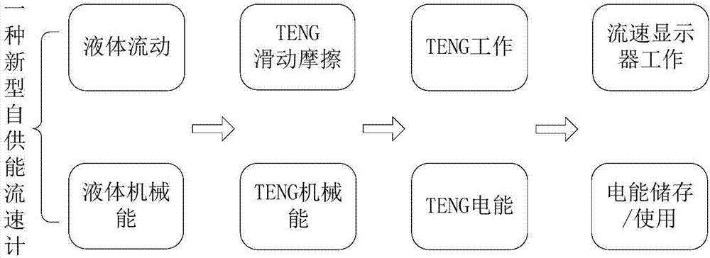
[0038] figure 1 Shown is an exploded schematic diagram of the basic structure of the self-powered liquid velocity meter of the present invention, figure 2 It is a schematic diagram of the overall structure of the self-powered liquid flow meter of the present invention. The flow meter includes: a housing 15, a turbine 13, a transmission shaft 14, a frictional nanometer generating mechanism 20, an energy storage mechanism 19, a digital display screen 2, and a pipeline system; wherein the housing 15 is a cylindrical cavity structure, and the cavity structure is The isolation plate 4 and the sealing plate 11 arranged successively from top to bottom are divided into an upper chamber, a middle chamber and a lower chamber 18; the energy storage mechanism 19 and the...
Embodiment 2
[0048] This embodiment is improved on the basis of Example 1. As a preferred embodiment of the present invention, on the basis of a self-powered liquid flow meter, a hydraulic sensor is set on the liquid inlet pipeline and the liquid outlet pipeline to form a New multifunctional liquid meter. The hydraulic sensor line passes out of the liquid inner cavity through the inner cavity of the flow meter, the sealing plate and the sealing hole on the sealing plate, and then connects to the circuit module in the circuit chamber through the friction nano power generation mechanism, the center hole of the friction plate and the line hole 5, Finally, the hydraulic information is converted into digital information and displayed on the display screen. The new multi-purpose self-powered liquid flow meter can also be used as a liquid meter. The invention can also be used as a liquid meter to measure the liquid temperature. A temperature sensor is embedded on the sealing plate of the inner c...
Embodiment 3
[0051] This embodiment is improved on the basis of Example 2. As a preferred embodiment of the present invention, on the basis of a self-powered liquid flow meter combined with GPS positioning technology, the network terminal replaces humans to realize automatic meter reading, thereby realizing The global network control of the entire water pipeline, through the collection and judgment of pipeline hydraulic temperature and other information, can detect pipeline resistance or liquid abnormalities in time, so that timely maintenance can be performed, and the impact of pipeline abnormalities on the pipeline system can be minimized as much as possible. In the present invention, the multi-purpose self-powered liquid flow meter has a collector inside, which can save the water meter data and intelligently transmit it to the Internet, and analyze and process the data through the background software operating system to form a smart water system.
[0052] Use the data acquisition system ...
PUM
 Abstract
Description
Claims
Application Information
 - R&D
- Intellectual Property
- Life Sciences
- Materials
- Tech Scout
- Unparalleled Data Quality
- Higher Quality Content
- 60% Fewer Hallucinations
Browse by: Latest US Patents, China's latest patents, Technical Efficacy Thesaurus, Application Domain, Technology Topic, Popular Technical Reports.
© 2025 PatSnap. All rights reserved.Legal|Privacy policy|Modern Slavery Act Transparency Statement|Sitemap|About US| Contact US: help@patsnap.com


