DC submodule

A technology of sub-modules and flow paths, applied in the field of power electronic modules, can solve problems that affect the service life and work efficiency of switches, reduce device voltage equalization, trigger consistency, response time, long closing time, etc., and achieve module voltage adjustment Quick and easy, simple voltage control, effect of reducing volume

Inactive Publication Date: 2017-07-25
HUAZHONG UNIV OF SCI & TECH
View PDF5 Cites 0 Cited by
  • Summary
  • Abstract
  • Description
  • Claims
  • Application Information

AI Technical Summary

Problems solved by technology

The current high-voltage switches are divided into mechanical switches and solid-state switches. Mechanical switches have high voltage levels and strong current-carrying capacity, but their response time and closing time are long, which is not conducive to the protection of power supplies; therefore, solid-state switches with IGBT and IGCT as the core The Switch Starts to Flourish
[0003] In order to be able to withstand high voltage levels, the usual solution is to directly connect semiconductor devices such as IGBTs in series. However, due to the subtle differences between each device and the influence of parasitic inductance of the line, the pressure on each device will be unbalanced during the switching process, which is extremely serious. The service life and working efficiency of the switch are greatly affected, resulting in device breakdown damage, and the damage of one device in the series link, even if there is redundancy, may cause the failure of the entire switch
In addition, in the field of HVDC power transmission, a new topology represented by Modular Multilevel Converter (MMC) has emerged, which adopts the design idea of ​​cascading sub-modules to improve the scalability of switches and reduce the To meet the requirements of device voltage equalization and trigger consistency, its sub-modules are usually full-bridge, half-bridge, and full-bridge structures. Since each sub-module needs to be charged in advance during work, and the state of the sub-module is switched by the control algorithm to actively change arm voltage, so none of these sub-module topologies are suitable for high voltage switching

Method used


Image

  • DC submodule
  • DC submodule
  • DC submodule

Examples


Embodiment Construction

[0034] In order to make the object, technical solution and advantages of the present invention clearer, the present invention will be further described in detail below in conjunction with the accompanying drawings and embodiments. It should be understood that the specific embodiments described here are only used to explain the present invention, not to limit the present invention. In addition, the technical features involved in the various embodiments of the present invention described below can be combined with each other as long as they do not constitute a conflict with each other.

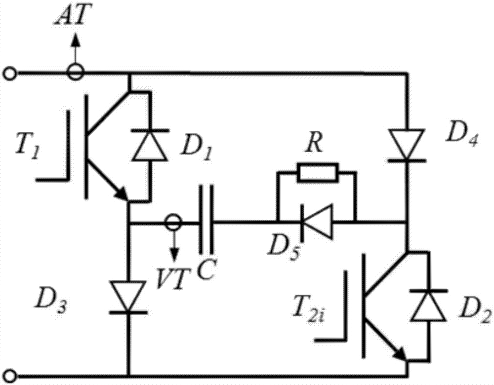
[0035] figure 1 As shown, it is a schematic diagram of the principle of the DC sub-module provided by the embodiment of the present invention; the DC sub-module includes a first IGBT T1, a second IGBT T 2i, a first diode D1, a second diode D2, and a third diode Tube D3, fourth diode D4, fifth diode D5, capacitor C, resistor R, current sensor AT and voltage sensor VT;

[0036] Among them, the I...


PUM


Abstract

The invention discloses a DC submodule, and the submodule comprises a first IGBT, a second IGBT, a first diode, a second diode, a third diode, a fourth diode, a fifth diode, a capacitor, a resistor, a current sensor, and a voltage sensor. The submodule achieves the switching among an energy releasing state, a locking state and an off state through controlling the switching of the two IGBTs, and completes the dynamic adjustment of a module voltage through the charging and discharging of the capacitor, thereby reducing the overvoltage damage risks of a module. In addition, when external equipment has a short-circuit fault, the submodule can instantly improve the through-current capability of the module through two parallel branch circuits, and inhibits the overcurrent damages. The submodule is simple in structure, is very high in flexibility, and can be applied in the field of high-voltage power switches through replacing the direct series connection of IGBTs with the cascading series connection of submodule units.

Description

technical field [0001] The invention belongs to the technical field of power electronic modules, and more specifically relates to a DC sub-module. Background technique [0002] With the continuous development of power electronics technology, the voltage and capacity of power supply equipment continue to increase. At present, in the fields of high-voltage inverters, direct current transmission, and nuclear fusion, the power supply voltage is mostly at the level of ten thousand volts or even hundreds of kilovolts. The reliability of this high-voltage equipment , High-performance operation is inseparable from a complete set of switch protection measures. The current high-voltage switches are divided into mechanical switches and solid-state switches. Mechanical switches have high voltage levels and strong current-carrying capacity, but their response time and closing time are long, which is not conducive to the protection of power supplies; therefore, solid-state switches with I...

Claims


Application Information

Patent Timeline
Patent Type & Authority Applications(China)
IPC IPC(8): H02M1/00
CPCH02M1/00H02M1/007
Inventor 张明王栋煜
Owner HUAZHONG UNIV OF SCI & TECH
Why Eureka
Try Eureka