Fluid kinetic energy collecting device for underwater vehicle

A technology of underwater vehicles and collection devices, which is applied in the direction of underwater operating equipment, machines/engines, piezoelectric effect/electrostrictive or magnetostrictive motors, etc., which can solve the problems of high energy transmission loss rate, numerous modules, The complex structure of the power generation system and other issues can achieve the effects of low energy storage and transmission loss rate, strong environmental adaptability, and simple device structure

Active Publication Date: 2017-07-28
HEFEI UNIV OF TECH
View PDF5 Cites 12 Cited by
  • Summary
  • Abstract
  • Description
  • Claims
  • Application Information

AI Technical Summary

Problems solved by technology

Although the device uses the dual effects of electromagnetic and photoelectricity to generate electricity, the entire power generation system has a complex structure, a large number of modules, and high production costs; the power generation module floats on the sea surface, while the energy storage module and the charging module are located underwater. Need to rely on long underwater cables to connect, the installation of the whole device is very inconvenient, and the practicability is poor; the device has been submerged in seawater for a long time, which has extremely high requirements on the waterproof performance and corrosion resistanc...

Method used


Image

  • Fluid kinetic energy collecting device for underwater vehicle
  • Fluid kinetic energy collecting device for underwater vehicle
  • Fluid kinetic energy collecting device for underwater vehicle

Examples


Embodiment Construction

[0027] The present invention will be further described through the embodiments below in conjunction with the accompanying drawings.

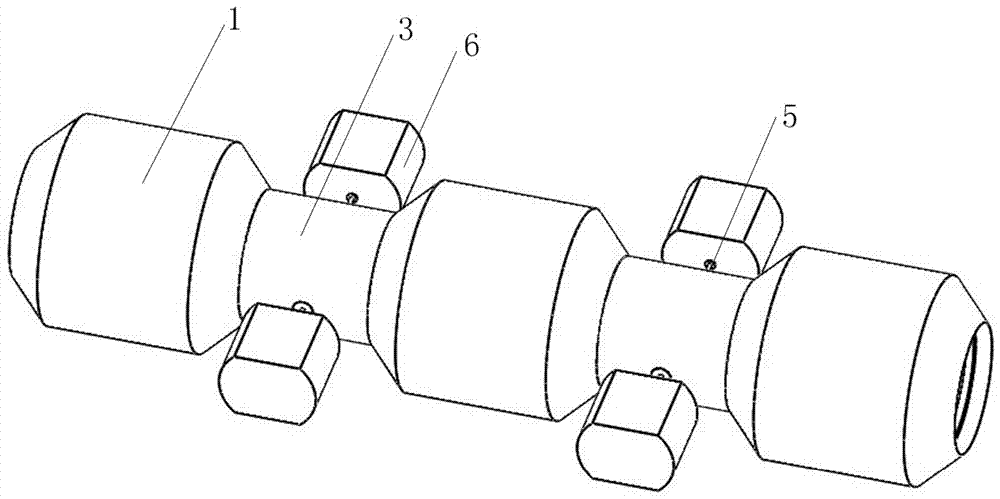
[0028] see figure 1 , a fluid kinetic energy collection device for an underwater vehicle includes a tubular body, the body is composed of three tubular vibration cabins 1 and two tubular water wheel cabins 3 alternately connected in series; the vibration cabin 1 and the water wheel cabin 3 The materials are all stainless steel. The diameter of the vibration cabin 1 is greater than that of the water wheel cabin 3, the diameter of the vibration cabin 1 is 644 mm, and the diameter of the water wheel cabin 3 is 400 mm.

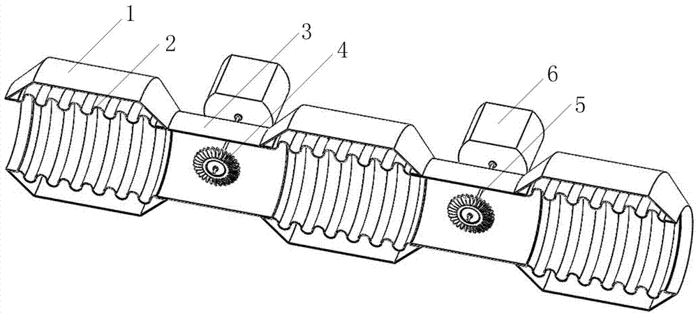
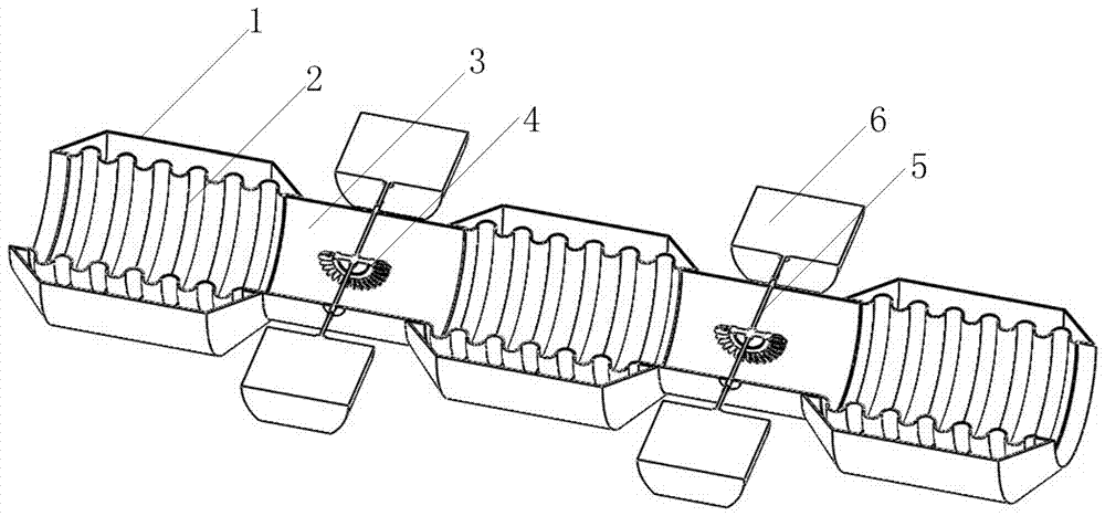
[0029] see figure 2 , image 3 , each vibrating chamber 1 is equipped with a bellows 2; the bellows 2 is a flexible tube, and the tube wall is composed of three layers of materials, the outer two layers are made of silica gel, and the inner layer is made of a flexible piezoelectric material. Electrodes are installed on the elec...


PUM

PropertyMeasurementUnit
Diameteraaaaaaaaaa

Abstract

The invention relates to a fluid kinetic energy collecting device for an underwater vehicle. The fluid kinetic energy collecting device comprises a tubular body. The body is formed by alternately connecting two or more vibration cabins with one or more water wheel cabins in series. The diameter of the vibration cabins is larger than that of the water wheel cabins. A corrugated pipe is arranged in each vibration cabin, and internally provided with a flexible piezoelectric material. Each water wheel cabin is internally provided with a water wheel through a rotation shaft, wherein the two ends of the rotation shaft stretch out of the two sides of the water wheel cabin. The two outward stretching ends of each rotation shaft are connected with the input ends of electromagnetic power generators correspondingly. During work, water flows in from one end of the body and flows out from the other end, the corrugated pipes in the vibration cabins are induced to vibrate, piezoelectric energy conversion is achieved, and electric energy output is achieved; and meanwhile, water flow drives the water wheels in the water wheel cabins to rotate, and then the electromagnetic power generators are driven to conduct electromagnetic power generation. The device is arranged in the underwater vehicle, the generated electric energy can be directly stored in a storage battery of the underwater vehicle, and the underwater vehicle can be charged in real time.

Description

technical field [0001] The invention belongs to the technical field of energy recovery, and in particular relates to a fluid kinetic energy collection device for an underwater vehicle. Background technique [0002] Ocean resources are huge and abundant, but underwater detection is difficult, and there are still many difficulties that are difficult to overcome. The development of underwater vehicles provides strong technical conditions for the development of marine resources. As a high-tech means, underwater vehicles play a vital role in ocean exploration, and the significance of developing underwater vehicles is obvious. At present, there are hundreds of underwater vehicles in the world, and underwater vehicles are active in many fields such as marine science, ocean engineering, underwater security and underwater warfare. [0003] Underwater vehicles are mainly powered by batteries, and the battery life is limited, which seriously restricts the development and application ...

Claims


Application Information

Patent Timeline
IPC IPC(8): F03B13/00F03B11/00B63C11/52H02N2/18
CPCB63C11/52F03B11/00F03B13/00H02N2/186Y02E10/20
Inventor 邓华夏杜宇王哲敏于连栋张进马孟超钟翔
Owner HEFEI UNIV OF TECH
Why Eureka
Try Eureka