Eureka AIR delivers breakthrough ideas for toughest innovation challenges, trusted by R&D personnel around the world.

an antenna system

An antenna system and stripline technology, used in antennas, resonant antennas, antenna arrays, etc., can solve the problems of unstable voltage standing wave ratio, complex structure design, and higher processing and assembly requirements.

Active Publication Date: 2021-08-20
HUAWEI TECH CO LTD
View PDF3 Cites 0 Cited by
  • Summary
  • Abstract
  • Description
  • Claims
  • Application Information

AI Technical Summary

Problems solved by technology

[0003] For antennas used in high-order multiple-input multiple-output technical scenarios, this conventional antenna structure design is more complicated and requires more assembly man-hours. Due to the large number of assembled components, it is easy to cause errors. Therefore, consistency will also be affected
[0004] The existing design scheme provides a feed system containing air microstrip lines, which uses reflectors as formations, which simplifies the design to a certain extent, but the air microstrip lines in this design scheme have obvious defects, namely : Large backward radiation, unstable voltage standing wave ratio, etc., and it is more than 2GHz frequency band because it has higher requirements for processing and assembly, so it is difficult to be adopted

Method used


Image

  • an antenna system
  • an antenna system
  • an antenna system

Examples


Embodiment 1

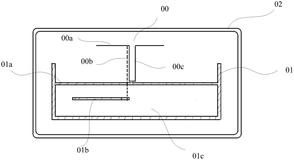
[0056] Such as figure 1 as shown, figure 1 It is a schematic side sectional view of a radiation unit connected to a stripline. In this embodiment, the radiation unit is a single-polarization radiation unit.

[0057] Specifically, such as figure 1 As shown, the radiating unit 00 includes a radiating arm 00a with a polarization direction, the radiating arm 00a is fixed on the top of the radiating balun 00c, and the radiating arm 00a corresponds to a feeding inner core 00b that is electrically fed to it, wherein the radiation The arm 00a and its corresponding feeding inner core 00b can be electrically coupled or welded for feeding connection. The stripline 01 has a hollow cavity 01c corresponding to the above-mentioned radiation arm 00a, and the stripline 01 has a stripline formation 01a corresponding to the radiation arm 00a in the same polarization direction, as shown in figure 1 As shown, the stripline formation 01a is the top side wall of the hollow cavity 01c. An inner c...

Embodiment 2

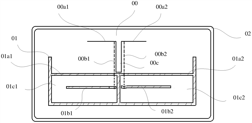
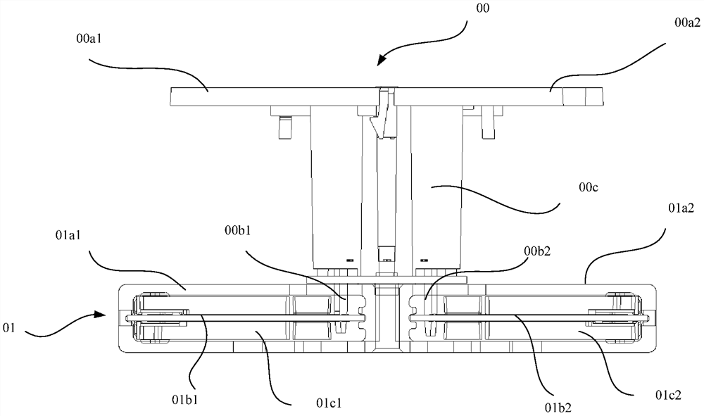
[0064] Such as figure 2 and image 3 It is shown that the antenna in the antenna system provided by this embodiment is a dual-polarized antenna, that is, the radiating unit 00 has radiating arms with two polarization directions, wherein figure 2 is a schematic side sectional view of the dual-polarized antenna, image 3 It is a cross-sectional view of the side structure of the dual-polarized antenna.

[0065] In this embodiment, the radiation unit 00 is a dual-polarized radiation unit, and the dual-polarized radiation unit includes a radiation arm whose polarization direction is positive 45° and a radiation arm whose polarization direction is negative 45°; Two inner conductors are arranged in the hollow cavity, and the radiation arm whose polarization direction is positive 45° is electrically connected to an inner conductor through the feeding inner core connected thereto, and the radiation arm whose polarization direction is negative 45° The feeder inner core via which it...


PUM


Abstract

The present invention relates to the technical field of communication, and discloses an antenna system, which includes: a radiation unit, at least one stripline formation and a signal cavity, and at least one inner conductor; the radiation unit includes a radiation arm, a radiation balun and Feed inner core; the stripline formation is used as the reflection surface of the radiation unit; the balun of the radiation unit is electrically connected to the stripline formation, and at least two radiation unit feed cores are electrically connected to an inner conductor at the same time, which can be used for very Conveniently optimize the feeding mode of the existing array antenna, greatly reduce the assembly time and reduce the number of solder joints and cables; increase consistency and reliability, and simplify the antenna by using the stripline ground as the reflective surface of the radiation unit The structure of the system.

Description

technical field [0001] The present invention relates to the technical field of communication, and in particular to an antenna system. Background technique [0002] At present, the interior of the radome in the conventional base station antenna design system mainly includes three parts, one is the radiation array unit, the other is the reflector that constrains the orientation, and the third is installed on the reflector to provide the amplitude and phase of the radiation array unit feed system. The reflector is usually used as a carrier platform, and the radiation array unit and the feed network are connected and installed together with the reflector. [0003] For antennas used in high-order multiple-input multiple-output technical scenarios, this conventional antenna structure design is more complicated and requires more assembly man-hours. Due to the large number of assembled components, it is easy to cause errors. Therefore, consistency will also be affected. [0004] ...

Claims


Application Information

Patent Timeline
IPC IPC(8): H01Q1/48H01Q3/44H01Q21/24
CPCH01Q1/246H01Q19/108H01Q21/0081H01Q3/32H01Q21/26H01Q1/36F16B5/02H01Q1/48H01Q3/44H01Q21/0075H01Q21/24H01Q9/065H01Q5/40H01Q21/28H01Q1/405H01Q9/06H01Q9/16H01Q19/17H01Q21/245
Inventor 肖伟宏廖志强
Owner HUAWEI TECH CO LTD
Why Eureka
Eureka Blog
Learn More