Welding machine with wire feeding and wire drawing being conducted alternately and power supply control method thereof

A welding machine power supply and control method technology, applied in manufacturing tools, welding equipment, arc welding equipment and other directions, can solve the problems of difficulty in welding thin plates and spatter, and achieve the effect of reducing arc heat and spatter

Active Publication Date: 2017-08-04
南京东斯达机电科技有限公司
View PDF7 Cites 1 Cited by
  • Summary
  • Abstract
  • Description
  • Claims
  • Application Information

AI Technical Summary

Problems solved by technology

[0006] Aiming at the problems of difficulty in welding thin plates and serious spatter of existing gas-shielded electric welding machines, the present invention provides an electric welding machine and a control method that can alternately change control modes. In...

Method used


Image

  • Welding machine with wire feeding and wire drawing being conducted alternately and power supply control method thereof
  • Welding machine with wire feeding and wire drawing being conducted alternately and power supply control method thereof
  • Welding machine with wire feeding and wire drawing being conducted alternately and power supply control method thereof

Examples


Embodiment 1

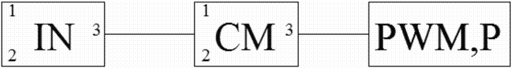
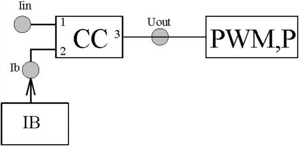
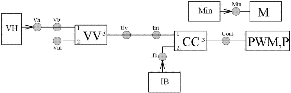
[0260] In this embodiment, VV and CC adopt image 3 Existing circuit modules in ;

[0261] Such as Figure 4 with Image 6 As shown, W0, W1, W2, W3, W4, W5, W6, W7, W8, W9, W10, W11 are potentiometers, U1, U2 are operational amplifiers 353, U3A is D flip-flop 4013, U4, U5 are single Steady-state flip-flop 4538;

[0262] A welding machine that alternately feeds and draws wire, adopts an analog control circuit, such as Image 6 As shown, one end of the potentiometer W0, W1, W2, W3, W4, W5, W6, W7, W8, W9, W10, W11 is connected to the power supply VCC, W0, W1, W2, W3, W4, W5, W6, W7, W10 , The other end of W11 is grounded, one end of resistors R1, R2, R3, and capacitor C1 is grounded, the middle end of W0 is connected to pin 1 of K6, the middle end of W1 is connected to pin 2 of K3, the middle end of W2 is connected to pin 1 of K3, and the middle end of W3 is connected to K2 The middle end of W4 is connected with pin 2 of K6, the middle end of W5 is connected with pin 5 of U...

Embodiment 2

[0277] A control method for a welding machine that alternately feeds and draws wire is basically the same as in Embodiment 1, the difference is that in step 4, D and F are connected, and the arc voltage reset mode ends the wire drawing stage and starts the next step Arcing stage: after Uh rises to a certain value, U2-1 becomes high, contact D is connected to contact F, the high level is sent to contact D through diode D4, U3 resets, U3-1 is low, and the wire feeder rotates forward , wire feeding, K1-15 is connected with K1-2, so that Uv is connected with Iin, and the arcing stage of stage 1 is repeatedly entered.

Embodiment 3

[0279] A control method for a welding machine that alternately feeds and draws wire, which is basically the same as Embodiment 1, the difference is that in step 4, the timing of the end of the retraction is reset by delay reset mode and arc voltage reset after the short circuit occurs The method is combined to end the spinning stage and start the next arcing stage;

[0280] Contact D is connected to contact E, and contact D is connected to contact F. "Delayed reset mode" and "arc voltage reset mode" exist at the same time, U4-7 first becomes high, which is "delayed reset mode"; U2-1 first changes High, for "arc voltage reset mode".


PUM


Abstract

The invention discloses a welding machine with wire feeding and wire drawing being conducted alternately and a power supply control method thereof, and belongs to the field of welding machine control systems. The problems that as for an existing gas-shielded electric welding machine, sheets cannot be welded easily and splashing is serious are solved. The power supply control method of the welding machine includes an arcing stage, a short-circuit stage and a drawing stage. At the arcing stage, a constant voltage control mode or a constant current control mode is adopted, and welding wires are fed in at a constant speed. At the short-circuit stage, the welding wires make contact with workpieces, the constant current control mode is adopted, and wire feeding is stopped. At the drawing stage, the constant current control mode or the constant voltage control mode is adopted for controlling the heating amplitude of the workpieces, and the welding wires are drawn at a constant speed. The welding wires are reset to the arcing stage after the drawing stage is completed. According to the welding machine with wire feeding and wire drawing being conducted alternately and the power supply control method thereof, different control mode circuits are used in different welding stages, and a wire feeder rotates forwardly or reversely in an associated mode for wire feeding or wire drawing, so that the effects of reducing arc heat, being capable of welding the sheets and reducing splashing are achieved.

Description

technical field [0001] The invention belongs to the field of welding machine control systems, and relates to a control method for reducing spatter and heat in MAG / MIG / CO2 gas shielded welding, in particular to a welding machine with alternate wire feeding and wire drawing and its power source control method. Background technique [0002] At present, the circuit of electric welding machine is as follows: figure 1 shown. In the figure, IN is the fixed circuit of the welding machine, which can be a potentiometer or a module with complex circuits. In the figure, CM is the control mode circuit, and the control mode circuit basically has two modes: CC mode (constant Current mode) and CV mode (constant voltage mode); PWM, P in the figure are pulse width modulators and inverters, common ones are 3523, 3846, 3875, etc., half-bridge inverters, full-bridge inverters, etc. The reason why there are different types of electric welding machines mainly depends on different types of CM. Fo...

Claims


Application Information

Patent Timeline
IPC IPC(8): B23K9/133B23K9/10
CPCB23K9/1012B23K9/1336
Inventor 鞠春盛石惟一石硕石蓓葛玲兰
Owner 南京东斯达机电科技有限公司
Why Eureka
Try Eureka