
Underwater rock plug blasting gyroscopic distributed chamber method

A distributed and gyroscopic technology, applied in blasting and other directions, can solve problems such as obvious clamping effect, large blasting vibration, and difficult to guarantee the size

Active Publication Date: 2017-08-08
CHINA WATER NORTHEASTERN INVESTIGATION DESIGN & RES
View PDF6 Cites 3 Cited by
  • Summary
  • Abstract
  • Description
  • Claims
  • Application Information

AI Technical Summary

Problems solved by technology

[0009] The invention provides a gyro-distributed drug chamber method for underwater rock plug blasting to solve the problems of large blasting vibration, obvious clamping effect, residual rock plug body, and difficulty in ensuring the shape and size of the opening

Method used


Image

  • Underwater rock plug blasting gyroscopic distributed chamber method
  • Underwater rock plug blasting gyroscopic distributed chamber method
  • Underwater rock plug blasting gyroscopic distributed chamber method

Examples


example 1

[0198] (1) Project overview

[0199] The sand discharge tunnel and expansion project of the Taohe Estuary in the Liujiaxia of the Yellow River, the water inlet adopts the underwater rock plug blasting technology, and the designed rock plug body is similar to an inverted truncated cone, the angle between the axis and the horizontal plane is 45°, and the angle between the busbar and the axis is 15° horn. The upper opening of the rock plug is elliptical, with a size of 21.60m×20.98m, the lower opening is circular, with a diameter of 10m, and the thickness of the rock plug is 12.30m.

[0200] The rock at the rock plug is mica-quartz schist, mainly weakly weathered rock, with a small amount of slightly weathered rock. The thickness of the weakly weathered rock is 2.0-6.0m, and the rock strength is relatively high. Saturation density 2820kg / m 3 , is hard rock, the rock is relatively complete, and belongs to type II rock (classified by 16, equivalent to 10).

[0201] The explosive...

example 2

[0267] (1) Project overview

[0268] A project field test shows that the rock mass slope at the entrance section is steep, the slope is generally 75°-85°, and reverse slopes are formed locally. The rock quality of the surrounding rock at the entrance section is hard, the rock is weak to slightly weathered, the surface rock integrity is poor, the average saturated compressive strength of the rock is 118MPa, and the average saturated bulk density of the rock is 2900kg / m 3 , belonging to Type II rock (classified according to 16 grades, equivalent to 10 grades), the lower opening of the designed rock plug is circular, the inner diameter is 7m, the outer opening is approximately elliptical, and the size is 11.96m×12.63m; the minimum thickness of the rock plug is 9.8m, and the rock plug The angle between the inlet axis and the horizontal plane is 72°, high-energy emulsion explosive is used, and the density is 1210kg / m 3 ;

[0269] (2) Rock plug pre-splitting hole

[0270] In orde...


PUM


Abstract

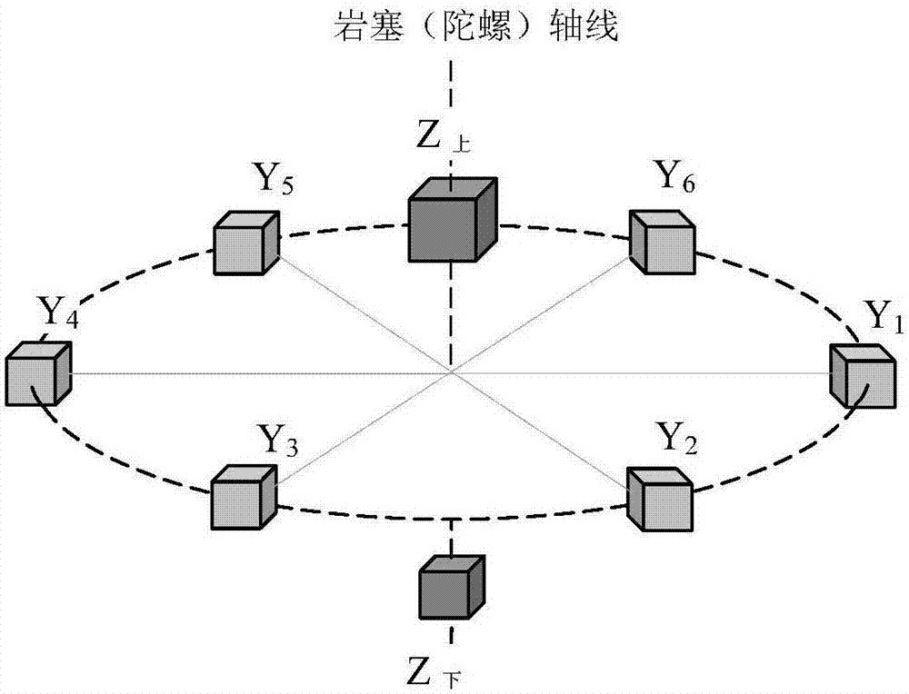
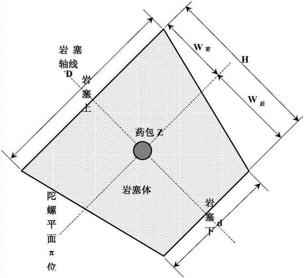
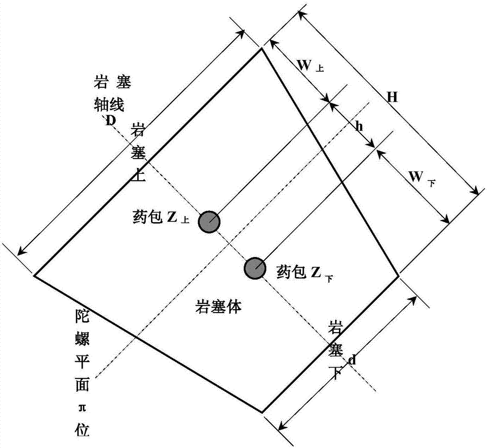
The invention relates to an underwater rock plug blasting gyroscopic distributed chamber method and belongs to rock plug body blasting methods in underwater rock plug blasting engineering. Presplit holes are drilled in the periphery of a rock plug according to the size of the rock plug body, the gyroscope plane position is worked out, the positions and explosive amount of an upper blasting cartridge Zupper and a lower blasting cartridge Zlower on the gyroscope axis are computed, the positions and the explosive amount of blasting cartridges Y1-Ym on the gyroscope plane are computed, layout of gyroscopic distributed chambers is finally determined, blasting of the chambers and a construction channel is conducted, and the blasting sequence and explosive time interval are set. The method has the advantages that the chambers are well arranged, the mutual relation of all the chambers is clear, the blasting mechanism and the action objects are specific, the structure is simple, and the method is easy to master; and the application prospects are wide, the gap between the large underwater rock plug blasting concentrated cartridge layout principle and practices is filled, and the method is a new breakthrough for underwater rock plug blasting chamber layout and has obvious practical application significances for underwater rock plug blasting design and construction.

Description

technical field [0001] The invention belongs to a rock plug body blasting method in underwater rock plug blasting engineering, and is suitable for underwater rock plug blasting projects at water intakes of water conservancy and hydropower projects and water diversion projects, and is also suitable for underwater rock plugs used in underground hangar passages of submarines blasting project Background technique [0002] Underwater rock plug blasting is an underwater controlled blasting technology. When water intake, power generation, irrigation water supply and flood discharge are carried out in built reservoirs or natural lakes, rock plugs are used to construct water intakes of tunnels and avoid building cofferdams in deep water. Blasting is an economical and effective method. [0003] At present, the traditional large-diameter underwater rock plug blasting mostly adopts decentralized chambers and layer-by-layer detonation methods, such as single-layer king-shaped and multi-...

Claims


Application Information

Patent Timeline
Patent Type & Authority Applications(China)
IPC IPC(8): F42D1/00F42D3/04
CPCF42D1/00F42D3/04
Inventor 苏加林王福运王鹤高垠姜殿成齐志坚张雨豪黄远泽朱奎卫蔡云波蔡光哲刘占军田伟峰齐立伟何国伟张彦东刘成浩马瑀泽于淼钟灿文韩闯郑希娟熊玲王佳奎
Owner CHINA WATER NORTHEASTERN INVESTIGATION DESIGN & RES
Learn More