Stop block type wall-attached jet valveless piezoelectric minipump
A wall-coated jet and block technology, applied in the field of microfluidic systems, can solve the problems of failing to control the flow direction, low volumetric efficiency of a valveless piezoelectric pump, unsatisfactory practical application effect, etc., and is conducive to miniaturization and shortening Design cycle and cost, the effect that is conducive to integration
- Summary
- Abstract
- Description
- Claims
- Application Information
AI Technical Summary
Problems solved by technology
Method used
Image

Examples
Embodiment Construction
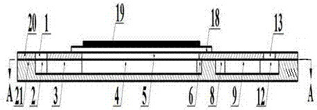
[0015] refer to Figure 1-3 As shown, the present invention includes a pump body 21, a pump cover 20, a piezoelectric vibrator 19 and a vibrating diaphragm 18. The material of the pump body 21 is silicon, the pump cover 20 is directly above the pump body 21, the material of the pump cover 20 is glass, and the pump body 21 and the pump cover 20 are tightly bonded together through a vacuum oxygen plasma bonding process.
[0016] like figure 2 , the filling pump port 1, the upper pump chamber 5, the first pump inlet 15, the second pump inlet 17 and the pump outlet 13 are processed on the pump cover 20, and the upper and lower heights of the structures processed on the pump cover 20 are equal to those of the pump cover 20. Same height up and down.
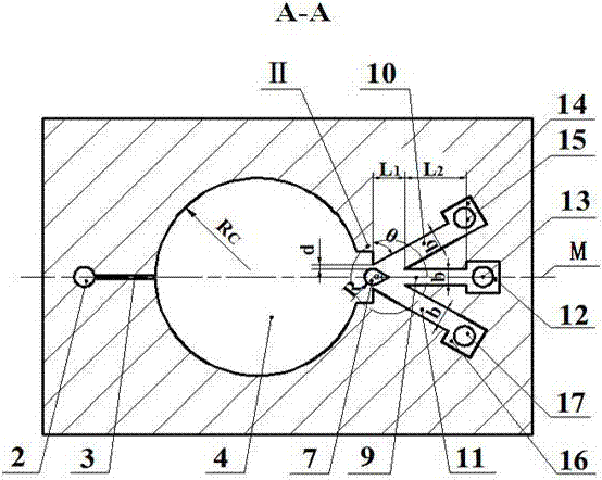
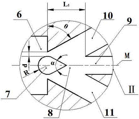
[0017] like image 3 On the pump body 21, the filling pump chamber 2, the filling pump pipe 3, the lower pump chamber 4, the attached wall part II, the first inlet direct pipe 10, the first pump inlet buffer chamber 14, the second ...
PUM
 Abstract
Description
Claims
Application Information
 - Generate Ideas
- Intellectual Property
- Life Sciences
- Materials
- Tech Scout
- Unparalleled Data Quality
- Higher Quality Content
- 60% Fewer Hallucinations
Browse by: Latest US Patents, China's latest patents, Technical Efficacy Thesaurus, Application Domain, Technology Topic, Popular Technical Reports.
© 2025 PatSnap. All rights reserved.Legal|Privacy policy|Modern Slavery Act Transparency Statement|Sitemap|About US| Contact US: help@patsnap.com