

Micro sensor packaging structure and manufacturing process thereof
A packaging structure and micro-sensor technology, applied in the field of micro-electromechanical systems, can solve the problems of high cost, poor stability, complex process, etc., to solve the problem of low-cost direct detection of liquid pressure and gas pressure, low manufacturing cost, accurate measurement the effect of the result
- Summary
- Abstract
- Description
- Claims
- Application Information
AI Technical Summary
Problems solved by technology
Method used
Image

Examples
Embodiment 1
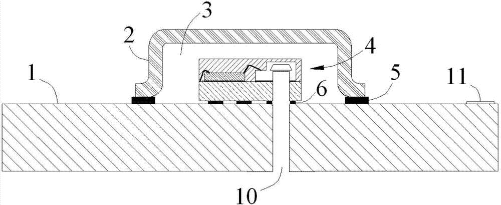
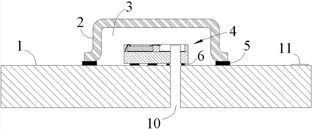
[0035] refer to figure 1 , figure 2 As shown, what it shows is the first embodiment of the present invention. The microsensor packaging structure in this embodiment includes a packaging base plate 1, a casing 2, and an accommodating chamber formed by enclosing the packaging bottom plate 1 and the casing 2. 3 Internal sensor module 4. The package base plate 1 is provided with a first through hole 10 penetrating through the package base plate 1 in the thickness direction, and the periphery of the casing 2 is arranged on the package base plate 1 in a sealed manner. A pressure sensor 42 and a circuit processing chip 43 on the substrate 41 .
[0036] More specifically, refer to figure 1 , figure 2 As shown, the substrate 41 is provided with a second through hole 410 penetrating through the substrate 41 in the thickness direction, the second through hole 410 communicates with the first through hole 10, and the pressure sensor 42 is disposed in the second through hole 410 away ...
Embodiment 2
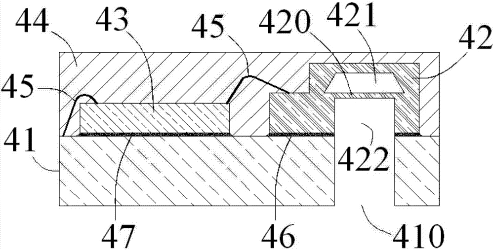
[0048] refer to image 3 , Figure 4 As shown, the main difference between the microsensor packaging structure shown in this embodiment and the microsensor packaging structure shown in Embodiment 1 is that the pressure sensor in this embodiment is a silicon piezoresistive differential pressure sensor. In this embodiment, The cladding layer 44 covers the connection interface between the silicon piezoresistive differential pressure sensor and the substrate 41 , and one surface of the pressure sensitive film 420 is exposed in the containing chamber 3 . Usually, an inert gas of a certain pressure (such as helium, nitrogen, etc.) is sealed inside the housing chamber 3 , and the specific pressure can be designed according to specific requirements. In a specific application process, the pressure difference on both sides of the pressure sensitive membrane 420 is the pressure on the pressure sensor 42 , and the circuit processing chip 43 can output the actual measured pressure after a...
Embodiment 3
[0050] In order to realize the micro-sensor packaging structure in the above embodiments, this embodiment specifically provides a manufacturing process of the micro-sensor packaging structure, which includes the following steps:
[0051] S1. Preliminary assembly of the sensor module, fixing the pressure sensor 42 and the circuit processing chip 43 on the same side of the substrate 41 and completing the electrical connection, wherein the substrate 41 is provided with a second through hole penetrating the substrate 41 in the thickness direction 410, the pressure sensor 42 is disposed at the position of the second through hole 410, and the pressure sensitive film 420 used for sensing pressure in the pressure sensor 42 is disposed opposite to the second through hole 410;
[0052] S2, sensor module molding, the substrate 41 that is fixed with pressure sensor 42, circuit processing chip 43 is placed in mold, injects resin, rubber, silica gel or other insulating materials in mold, has...
PUM
 Abstract
Description
Claims
Application Information