Charging loop for internal resistance compensation of wind turbine generator set variable-pitch super capacitor, and control method thereof

A technology of supercapacitors and wind turbines, applied in battery circuit devices, circuit devices, collectors, etc., can solve problems such as limited capacitive response and response ability, limited compensation effect, etc.

Pending Publication Date: 2017-08-15
HUADIAN ELECTRIC POWER SCI INST CO LTD
View PDF12 Cites 2 Cited by
  • Summary
  • Abstract
  • Description
  • Claims
  • Application Information

AI Technical Summary

Problems solved by technology

The compensation effect of this scheme is limited, and the response and response ability to the problem of capacitance is limited

Method used


Image

  • Charging loop for internal resistance compensation of wind turbine generator set variable-pitch super capacitor, and control method thereof
  • Charging loop for internal resistance compensation of wind turbine generator set variable-pitch super capacitor, and control method thereof
  • Charging loop for internal resistance compensation of wind turbine generator set variable-pitch super capacitor, and control method thereof

Examples


Embodiment 1

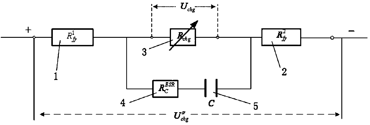
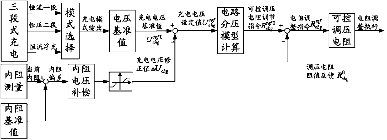
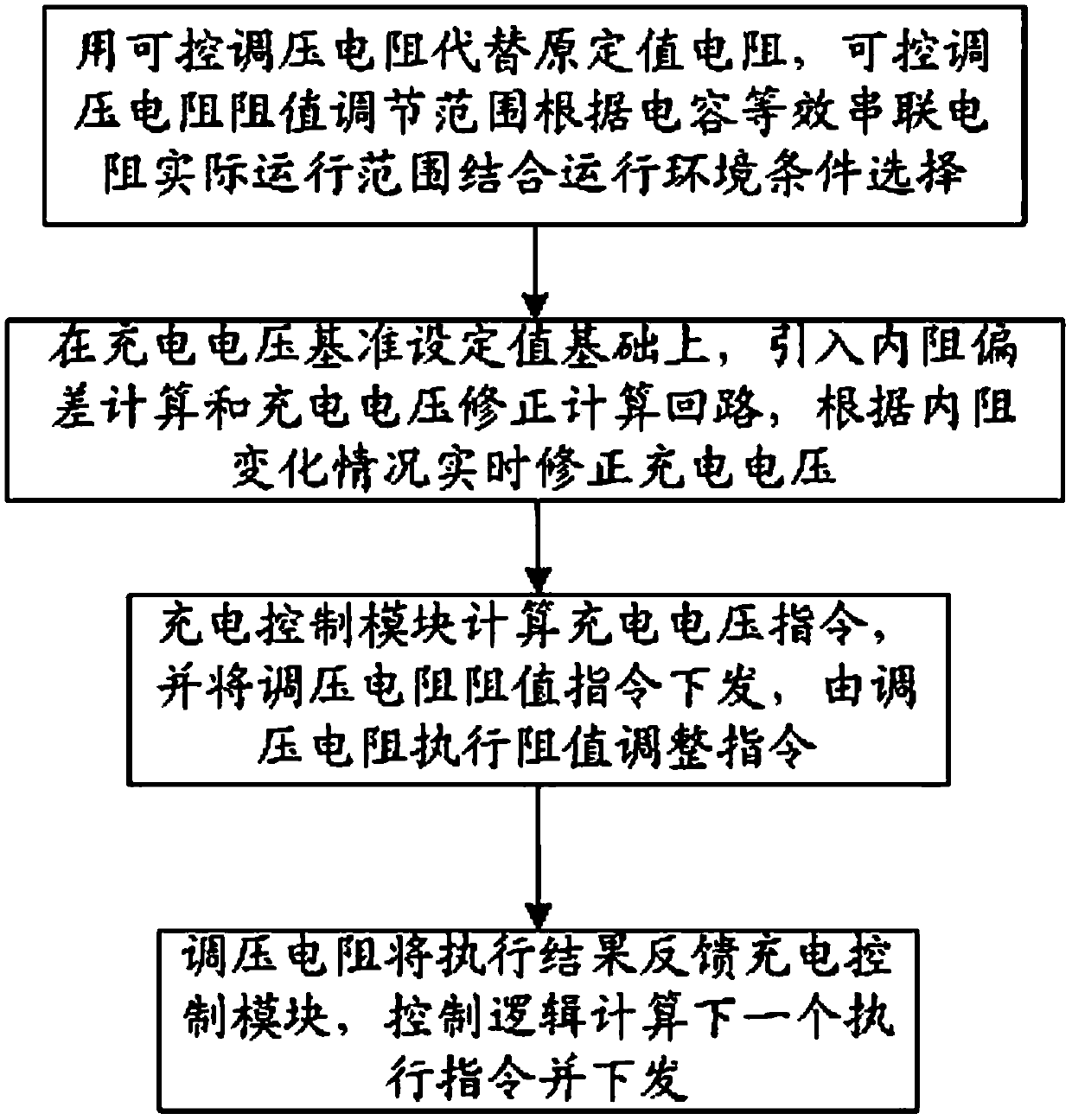
[0034]This embodiment is a charging circuit for internal resistance compensation of a wind turbine pitch supercapacitor, including two voltage divider resistors and a resistor, the two voltage divider resistors are No. 1 voltage divider resistor 1 and No. 2 voltage divider resistor 2, and a The series resistance between No. 1 and No. 2 voltage dividing resistors is a controllable voltage regulating resistor 3, and the two ends of the controllable voltage regulating resistor 3 are connected in parallel with an internal resistance detection circuit, and the internal resistance detection circuit is connected with the controllable voltage regulation The resistors 3 are connected in parallel, and the parallel circuit composed of the internal resistance detection circuit and the controllable voltage regulating resistor 3 is connected in series between the No. 1 voltage dividing resistor 1 and the No. 2 voltage dividing resistor 2 . The internal resistance detection circuit is a super...

Embodiment 2

[0055] The temperature difference between winter and summer in a wind farm in Ningxia is 30°C. The measured temperature difference of the backup power supply shell in winter and summer is more than 50°C. Switching power supply output for voltage trimming. Install the internal resistance detector and run it for one year. Taking the internal resistance corresponding to 25°C as the reference internal resistance, and making monthly statistics, the measured actual internal resistance fluctuates within the range of 25%-30% above and below the reference.

[0056] According to the original charging circuit, the adjustment range of the resistance value of the controllable voltage regulating resistor 3 is calculated to be 0 to 1.43 times the original nominal resistance, and accordingly the adjustment range of the resistance value of the controllable voltage regulating resistor 3 is 0 to 1.5 times the original nominal resistance, and replaced In the charging circuit, the original fixed v...


PUM


Abstract

The invention relates to a charging loop for internal resistance compensation of a wind turbine generator set variable-pitch super capacitor. The charging loop comprises two voltage-dividing resistors and a resistor, wherein the two voltage-dividing resistors comprise a voltage-dividing resistor 1 and a voltage-dividing resistor 2, and the resistor is connected between the voltage-dividing resistor 1 and the voltage-dividing resistor 2 in series. The charging loop is characterized in that the resistor is a voltage-regulating resistor, both ends of the voltage-regulating resistor are connected with an internal resistance detection loop in parallel, the internal resistance detection loop is connected with the voltage-regulating resistor in parallel, and a parallel circuit formed by the internal resistance detection loop and the voltage-regulating resistor is connected between the voltage-dividing resistor 1 and the voltage-dividing resistor 2 in series. The invention further relates to a charging loop control method for internal resistance compensation of the wind turbine generator set variable-pitch super capacitor.

Description

technical field [0001] The invention relates to a charging circuit and a control method for internal resistance compensation of a pitch-pitching supercapacitor of a wind turbine, and belongs to the field of wind turbine operation control. Background technique [0002] Wind power is currently a form of energy utilization with relatively mature technology, a high degree of practicality, strong commercial development value and strong market competitiveness. The grid-connected installed capacity is close to 140 million kilowatts. With the rapid growth of the scale, the industry's attention to the reliability of the unit equipment operation has gradually increased. According to preliminary statistics, the power loss due to the failure of the wind turbine accounted for 1% to 3% of the theoretical power generation of the unit. Defects and failures of the propeller system account for a considerable proportion, among which the damage to the pitch converter, pitch motor, slip ring, a...

Claims


Application Information

Patent Timeline
Patent Type & Authority Applications(China)
IPC IPC(8): H02J7/00H02J7/34
CPCH02J7/0077H02J7/345
Inventor 柴海棣钟天宇张伟付立
Owner HUADIAN ELECTRIC POWER SCI INST CO LTD
Why Eureka
Try Eureka