
MIMO (Multiple-input Multiple-output) radar angle estimation algorithm based on tensor subspace and rotation invariant

A rotation invariant, angle estimation technology, applied in the field of MIMO radar angle estimation algorithms, can solve the problems affecting the angle estimation accuracy, low computational complexity, inaccurate GPE estimation, etc., and achieve high angle estimation accuracy and low computational complexity. Effect

Active Publication Date: 2017-08-18
YANGTZE UNIVERSITY
View PDF5 Cites 20 Cited by
  • Summary
  • Abstract
  • Description
  • Claims
  • Application Information

AI Technical Summary

Problems solved by technology

Liu Xiaoli and others proposed a MUSIC-Like algorithm (Liu Xiaoli, Liao Guisheng. Bistatic MIMO radar multi-target positioning and amplitude-phase error estimation [J]. Electronic Journal, 2011, 39(3):596-601), but the algorithm only The relevant data of the first transceiver array element is used, and the angle estimation aperture is not effectively used
Moreover, the downsampling and iterative method of the calculation and the MUSIC idea are used to estimate the angle, and the computational complexity is high; Li et al. proposed a dimensionality reduction MUSIC (RD-MUSIC) algorithm (J.Li, X.Zhang, R.Cao, et al .Reduced-dimension music for angle and array gain-phase error estimation in bistatic MIMO radar[J],IEEE Communications Letters,2013,17(3):443-446), the algorithm is not sensitive to the position of the calibrated array element, And it is suitable for non-uniform arrays, but the algorithm needs to search for spectral peaks, so its computational complexity is high, and there will be grid mismatch problems; Guo et al. proposed an ESPRIT-Like algorithm (Y.D.Guo, Y.S.Zhang, N.N. Tong.Esprit-like angle estimation forbistatic MIMO radar with gain and phase uncertainties[J],Electronics Letters,2011,47(17):996-997), which uses the rotation invariance of the array for angle estimation, and has low computational complexity; Both the RD-MUSIC algorithm and the ESPRIT algorithm use the subspace of the received signal for parameter estimation, which requires eigenvalue decomposition (Eigenvalue Decomposition, EVD) of the received data, and the computational complexity is high. Chen et al. proposed an algorithm without EVD ——PM-Like Algorithm (C.Chen,X.F.Zhang.Joint angle and array gain-phase error estimation using PM-like algorithm for bistatic MIMO radar[J],Circuits SystemSignal Process,2013,32(3):1293-1311) , which has lower computational complexity than the ESPRIT-Like algorithm; Li et al. proposed an improved ESPRIT (I-ESPRIT) algorithm (J.Li, M.Jin, Y.Zheng, G.Liao, Transmit and receive array gain phase error estimation in bistatic MIMO radar[J],IEEEAntennas and Wireless Propagation Letters,2015 ,14:32-35), the algorithm does not need to estimate the GPE, and the computational complexity is low
However, I-ESPRIT only uses the received data of two calibrated transmitting and receiving array elements, and its angle estimation process is sensitive to noise, and the algorithm requires additional pairing of estimated parameters; in order to utilize the internal multidimensional characteristics of array data , Li et al proposed a PARAFAC-Like algorithm (J.Li, X.F.Zhang, X.Gao.A joint scheme for angle and array gain phase error estimation in bistatic MIMO radar[J], IEEE Geoscience and Remote Sensing Letters.2013, 10(6):1478-1482), but the algorithm first needs to estimate the GPE of the array, and the error in the process of estimating the GPE has a cumulative effect, which makes the GPE estimation often inaccurate, thus affecting the accuracy of its angle estimation

Method used

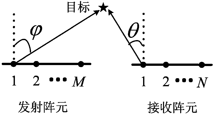
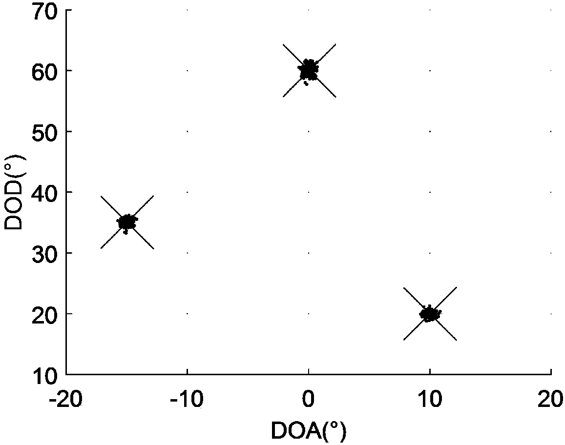
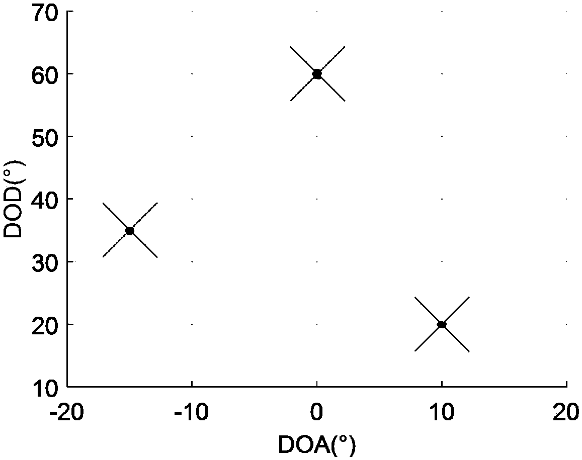

Image

  • MIMO (Multiple-input Multiple-output) radar angle estimation algorithm based on tensor subspace and rotation invariant
  • MIMO (Multiple-input Multiple-output) radar angle estimation algorithm based on tensor subspace and rotation invariant
  • MIMO (Multiple-input Multiple-output) radar angle estimation algorithm based on tensor subspace and rotation invariant

Examples


Embodiment Construction

[0020] In order to make the objectives, technical solutions and advantages of the present invention clearer, the present invention will be described in further detail below in conjunction with the accompanying drawings and embodiments. It should be understood that the specific embodiments described here are only used to explain the present invention and are not intended to limit the invention.

[0021] The present invention provides a MIMO radar angle estimation algorithm based on tensor quantum space and rotation invariance. The MIMO radar angle estimation algorithm based on tensor quantum space and rotation invariance includes the following steps:

[0022] S1. Construct a third-order tensor model of the target echo signal, and construct a high-order covariance tensor model of the received signal through the tensor model structure;

[0023] S2. Perform high-order singular value decomposition on the high-order covariance tensor model, and construct a new signal subspace to obtai...


PUM


Abstract

The invention discloses a MIMO (Multiple-input Multiple-output) radar angle estimation algorithm based on tensor subspace and rotation invariant. Through building a three-order tensor model for receiving data, a higher-order covariance tensor model for tensor data is further built, and the internal correlation structure of array signals is thoroughly exploited; HOSVD (Higher Order Singular Value Decomposition) is then carried out on the tensor data, new signal subspace is built, and high-precision noise subspace is thus acquired; and finally, by using the rotation invariant of array data, a DOD (Direction of Departure) and a DOA (Direction of Arrival) which are paired are acquired through a constrained optimization method and a lagrangian multiplier method, and further pairing calculation is not needed. According to the MIMO radar angle estimation algorithm of the invention, by using the internal correlation structure of the received signals, the angle estimation precision is higher, the target DOD and the target DOA which are more accurate can be acquired, a more reasonable reference is provided for further processing on a detected target, spectral peak search is not needed, and the computation complexity is low.

Description

technical field [0001] The invention relates to a radar signal processing technology, in particular to a MIMO radar angle estimation algorithm based on tensor quantum space and rotation invariance. Background technique [0002] Multiple-input Multiple-output (MIMO) radar is a new radar system, which uses multiple array elements to transmit and receive signals synchronously. Compared with traditional phased array radar systems, MIMO radar has potential advantages in terms of resolution, anti-fading, identifiability, and noise suppression. MIMO radars can be divided into two types according to the position distribution of the transmitting and receiving elements of MIMO radars: statistical MIMO radars and co-located MIMO radars. Among them, the statistical MIMO radar sampling distributed transceiver array configuration can effectively suppress the scintillation effect of the target; the transmitting array element and receiving array element in the co-located MIMO radar are oft...

Claims


Application Information

Patent Timeline
IPC IPC(8): G01S7/41
CPCG01S7/41
Inventor 文方青陈伟国李修权盛冠群李飞涛
Owner YANGTZE UNIVERSITY
Learn More