Method for improving wear resistance and rolling contact fatigue performance of steel rails
A technology of rolling contact fatigue and wear resistance, which is applied in the coating process and coating of metal materials, can solve the problems of rolling contact fatigue performance, wear resistance, crack porosity, and cladding layer unevenness, etc. Achieve the effects of strong grain dislocation, reduced stress, and uniform distribution of eutectic structure
- Summary
- Abstract
- Description
- Claims
- Application Information
AI Technical Summary
Problems solved by technology
Method used
Image
Examples
Embodiment 1
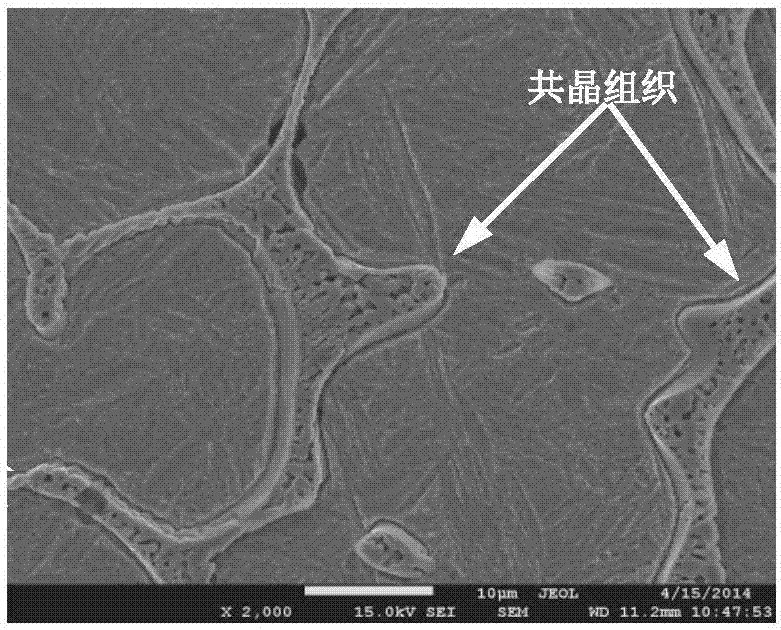
[0024] A method for improving the wear resistance and rolling contact fatigue performance of rails is to use a laser to clad Fe-based powders on the surface of the rails under argon protection, and it is characterized in that: the Fe-based alloy powders are Fe-based alloy powders. Fe-based alloy powder composed of lanthanum oxide powder with a mass content of 0.4% is added to the powder; the particle size of the Fe-based alloy powder is 50 mesh.
[0025] In this example, the laser is used to clad the Fe-based powder on the surface of the rail. The specific method is: the laser is a multi-mode cross-flow CO 2 Laser, the laser power is 2.8kw, the scanning speed is 200mm / min, the rectangular spot size of the laser beam is 1mm×7mm, the defocus is 31mm, and the powder feeding speed is 15g / min.
Embodiment 2
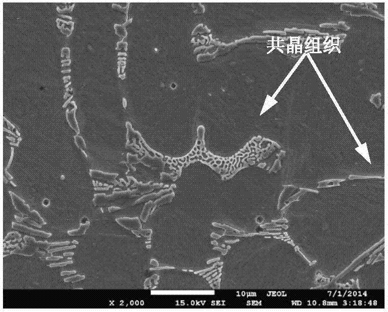
[0027] A method for improving the wear resistance and rolling contact fatigue performance of rails is to use a laser to clad Fe-based powders on the surface of the rails under argon protection, and it is characterized in that: the Fe-based alloy powders are Fe-based alloy powders. Fe-based alloy powder composed of lanthanum oxide powder with a mass content of 1.2% is added to the powder; its particle size is 100 mesh.
[0028] In this example, the laser is used to clad the Fe-based powder on the surface of the rail. The specific method is: the laser is a multi-mode cross-flow CO 2 For the laser, the laser power is 3.0kw, the scanning speed is 220mm / min, the rectangular spot size of the laser beam is 1mm×7mm, the defocus is 30mm, and the powder feeding speed is 10g / min.
Embodiment 3
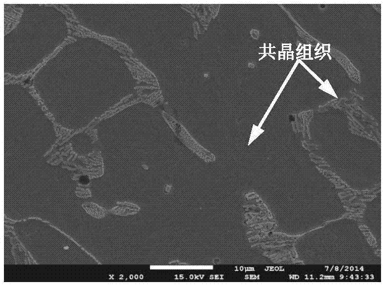
[0030] A method for improving the wear resistance and rolling contact fatigue performance of rails is to use a laser to clad Fe-based powders on the surface of the rails under argon protection, and it is characterized in that: the Fe-based alloy powders are Fe-based alloy powders. Fe-based alloy powder composed of lanthanum oxide powder with a mass content of 2% is added to the powder; the particle size is 200 mesh.
[0031] In this example, the laser is used to clad the Fe-based powder on the surface of the rail. The specific method is: the laser is a multi-mode cross-flow CO 2 Laser, laser power 2.9kw, scanning speed 210mm / min, laser beam rectangular spot size 1mm×7mm, defocus amount 32mm, powder feeding speed 20g / min.
PUM
| Property | Measurement | Unit |
|---|---|---|
| Granularity | aaaaa | aaaaa |
Abstract
Description
Claims
Application Information
 - R&D
- Intellectual Property
- Life Sciences
- Materials
- Tech Scout
- Unparalleled Data Quality
- Higher Quality Content
- 60% Fewer Hallucinations
Browse by: Latest US Patents, China's latest patents, Technical Efficacy Thesaurus, Application Domain, Technology Topic, Popular Technical Reports.
© 2025 PatSnap. All rights reserved.Legal|Privacy policy|Modern Slavery Act Transparency Statement|Sitemap|About US| Contact US: help@patsnap.com


