Gas-liquid two-phase flow measuring device and method based on phase segmentation and image processing

A flow measurement device, gas-liquid two-phase flow technology, applied in the direction of measurement devices, liquid/fluid solid measurement, flow/mass flow measurement, etc., can solve the problem of low resolution of soft field characteristics, poor real-time measurement, and signal nonlinearity Analyzing and other problems to achieve the effect of overcoming the difficulty in determining the gas content of the section, saving material costs, and improving the resolution

Active Publication Date: 2017-08-29
XI AN JIAOTONG UNIV
View PDF9 Cites 28 Cited by
  • Summary
  • Abstract
  • Description
  • Claims
  • Application Information

AI Technical Summary

Problems solved by technology

However, the existing measurement methods have different degrees of shortcomings. For example, the traditional separation method is to completely separate the two-phase fluid and then measure each phase separately to finally determine the total flow rate. This method is stable and reliable in measurement principle. The method adopted in CN101025080A is to carry out natural sedimentation and separation by gravity and then measure separately, but in order to ensure the separation effect, it usually needs bulky, complex structure separation equipment and poor real-time measurement, and needs to maintain the stability of the liquid level at all times; the differential pressure method is The flow rate is determined by measuring the differential pressure signal of the two-phase flow passing through the throttling device to construct a correlation equation with the gas-liquid two-phase fluid flow rate. For example, the method adopted by the publication number CN102252722A is to correlate the two-phase fluid flow rate by measuring multiple differential pressure signals. , but due to the small range of the differential pressure transmitter, the flow range of the two-phase fluid that can be measured will be greatly limited, and the measurement signal of the differential pressure transmitter will vary with the flow pattern and cross-sectional content of the two-phase fluid Non-linear changes due to changes in characteristic parameters such as gas rate, these factors will lead to measurement errors
The method adopted in the publication number CN104121955A is to separate the liquid-liquid two-phase flow through the phase separation and then use the ultrasonic method to determine the cross-section of each phase and the average flow velocity to finally determine the flow of the two-phase fluid. However, the propagation speed of the sound wave is affected by various factors such as temperature. Influence, which in turn will cause measurement errors, and these errors are not easy to find and correct
Publication number CN101871906 uses electrical tomography to determine the distribution of phases in the pipeline based on the feedback signal of the electromagnetic excitation signal in the pipeline, and then determines the distribution of each phase in the pipeline through image reconstruction. However, due to the complex and diverse distribution of two-phase flow, when The severely nonlinear feedback signal after the excitation signal passes through the overlapping gas and liquid interfaces will make the image reconstruction algorithm very complicated, and the soft field characteristics of electrical tomography will lead to low resolution
Publication No. EP0225741 B1 is to determine the flow conditions of the two-phase flow in the pipe, especially the cross-section gas fraction, by measuring the signal after the gamma ray penetrates the two-phase flow. Although the gamma ray is different from the soft field characteristics of electrical tomography, it is There is also the problem that the signal is severely nonlinear and the analysis is complicated due to the diverse and complex flow patterns of the two-phase flow
The patent of Publication No. CN104457703A adopts a method of arranging multiple high-speed cameras at the same position of the pipeline, connected with multiple light sources and correspondingly surrounding the transparent measurement pipeline of the small pipeline to obtain two-dimensional images and reconstruct the three-dimensional flow state to obtain two-phase Fluid parameters. In this method, a camera is used to directly capture the flow state in the tube, and then the required flow parameters are obtained through image processing and analysis. The image analysis and processing method can improve the resolution. The transition, transition and other states between them lead to a very high degree of complexity in directly capturing the original flow state image of the two-phase fluid, and the image processing algorithm also becomes complex and inefficient.
Publication No. US20020176606 A1 uses the PIV (Particle Image Velocimetry) method to measure the size and velocity of the entrained phase (particles) in the two-phase flow and then determine the mass flow rate of the entrained phase. This method uses PIV to measure the velocity and particle size with high measurement accuracy , however, the measured two-phase flow is still in a natural flow state. Since the two-phase flow has many complex flow patterns, the two-dimensional plane PIV can only capture the flow state of the two-phase flow on a certain plane, and only according to the The flow state analysis data to measure the total mass flow rate of the entrained phase has a certain one-sidedness, which will lead to measurement errors

Method used


Image

  • Gas-liquid two-phase flow measuring device and method based on phase segmentation and image processing
  • Gas-liquid two-phase flow measuring device and method based on phase segmentation and image processing
  • Gas-liquid two-phase flow measuring device and method based on phase segmentation and image processing

Examples


Embodiment Construction

[0036] The present invention will be described in more detail below in conjunction with the accompanying drawings.

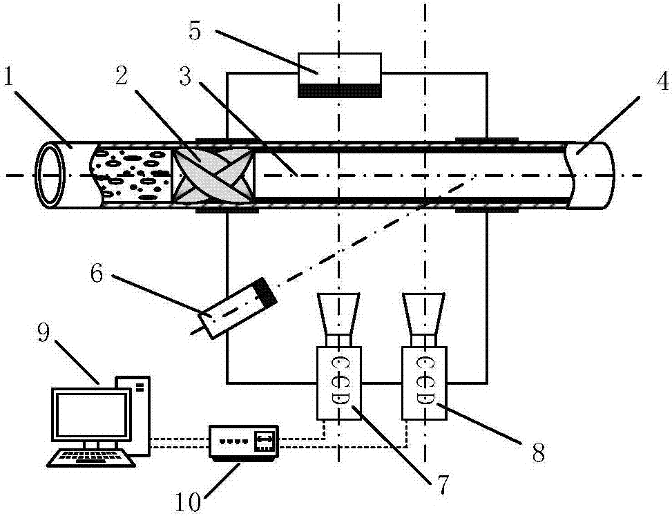
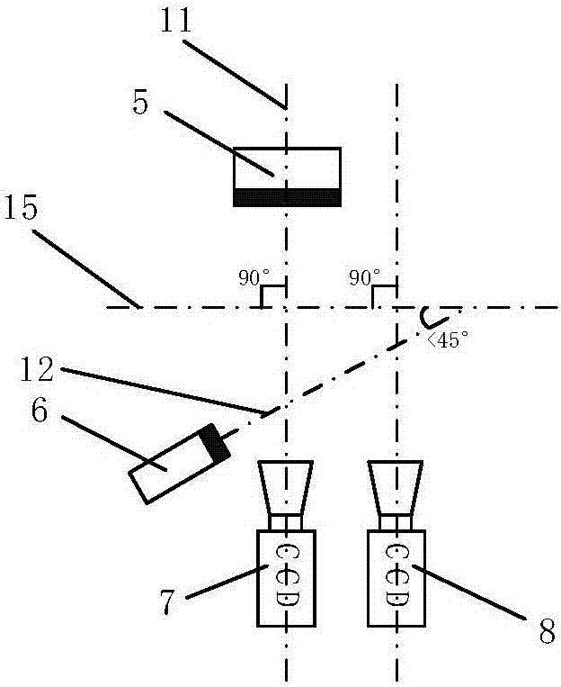
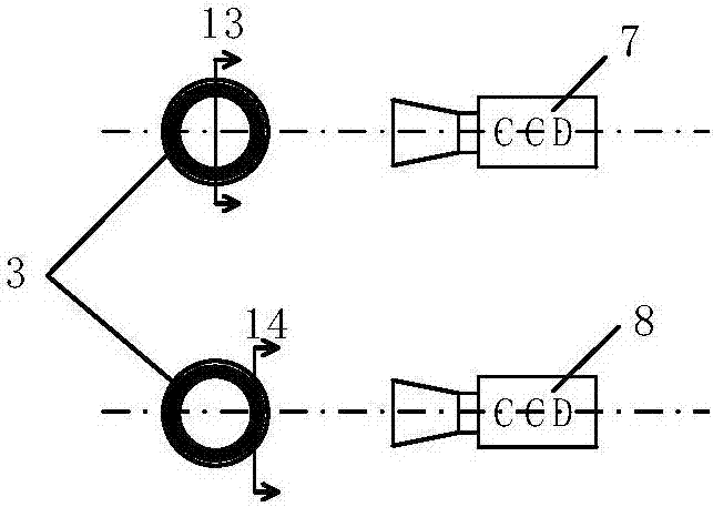
[0037] Such as figure 1 As shown, the present invention is a gas-liquid two-phase flow measurement device and method based on phase separation and image processing, wherein the measurement device includes an inlet section 1, a measuring pipe section 3 and an outlet section 4, all of which are made of light-transmitting materials, which are sequentially connected. , the swirl device 2 is fixed on the inner wall of the measuring pipe section 3, and the swirl device 2 is relatively stationary with the measuring pipe section 3; it also includes an industrial camera-7 and an opposite parallel light source 5 respectively arranged on both sides of the measuring pipe section 3, arranged on The second industrial camera 8 and the parallel light source 6 on the same side of the measuring pipe section 3, the synchronous controller 10 connected to the first industrial camera...


PUM


Abstract

The invention discloses a gas-liquid two-phase flow measuring device and method based on phase segmentation and image processing. The device is composed of an inlet section, a rotational flow device, a measuring pipe section, an outlet section, an opposite-side parallel light source, a same-side parallel light source, a first industrial camera, a second industrial camera, an image collecting and processing terminal and a synchronous controller. The invention further provides a measuring method. The method comprises the steps of firstly using the rotational flow device to rectify gas-liquid two-phase flow into a flower pattern which is convenient to measure through an in-pipe phase segmentation technology, then combining a digital image processing technology to accurately measure cross section gas void faction of the gas-liquid two-phase flow and flow velocity of each phase, and finally calculating the mass flow rate of each phase and the total mass flow rate of two-phase fluid. Compared with existing equipment and method, the gas-liquid two-phase flow measuring device based on phase segmentation and image processing has the advantages of being small in volume, high in instantaneity and high in accuracy; meanwhile, the gas-liquid two-phase flow measuring device and method are not influenced by the flow pattern of the gas-liquid two-phase fluid, and thus can be widely applied in engineering. Since the gas-liquid two-phase flow measuring method is not influenced by gravity, the gas-liquid two-phase flow measuring method is also applied to a zero-gravity environment.

Description

technical field [0001] The invention belongs to the technical field of flow measurement, and in particular relates to a gas-liquid two-phase flow flow measurement device and method based on phase separation and image processing. Background technique [0002] Gas-liquid two-phase fluid is different from single-phase fluid. It is not composed of two fluids uniformly mixed but composed of two fluids with different physical properties flowing together. The two-phase flow rates are different and have a clear interface. Therefore, the accurate measurement of the gas-liquid two-phase flow requires accurate measurement of the flow of the two-phase fluid respectively. However, due to the diversification of gas-liquid two-phase flow patterns, its flow state is also easily affected by many factors, and there may be interactions and phase changes between the two phases, which make the flow measurement of gas-liquid two-phase fluid It is much more complicated than single-phase fluid flo...

Claims


Application Information

Patent Timeline
Patent Type & Authority Applications(China)
IPC IPC(8): G01F1/66
CPCG01F1/661
Inventor 牛棚满王栋杨杨卫鹏凯史红卫
Owner XI AN JIAOTONG UNIV
Why Eureka
Try Eureka