Shaft-vibration forced mixer

A mixer and shaft vibration technology, which is applied in the fields of cement mortar and asphalt mixture mixers, cement concrete, and cement stabilized soil, can solve the problems of large vibration power loss, effect of effective mixing volume, poor stability and durability, etc.

Pending Publication Date: 2017-09-01
归立发
View PDF6 Cites 11 Cited by
  • Summary
  • Abstract
  • Description
  • Claims
  • Application Information

AI Technical Summary

Problems solved by technology

But, there is weak point in the mixer of this structure: the rigidity of hollow shaft reduces along with the length of stirring shaft, if increase the wall thickness of stirring shaft in order to increase rigidity, stirring shaft diameter will be done very big, the effective of mixing drum The mixing volume is affected, and the direct manufacturing cost and associated cost will be greatly increased; and the structure is complex, the stability and durability are poor, and the maintenance cost is high
However, this structure also has the following deficiencies: first, because one end of the stirring shaft is the input end of the stirring power, other parts are fixed or stationary except for the rotation of the stirring shaft, and the other end is the vibrat

Method used


Image

  • Shaft-vibration forced mixer
  • Shaft-vibration forced mixer
  • Shaft-vibration forced mixer

Examples


Embodiment 1

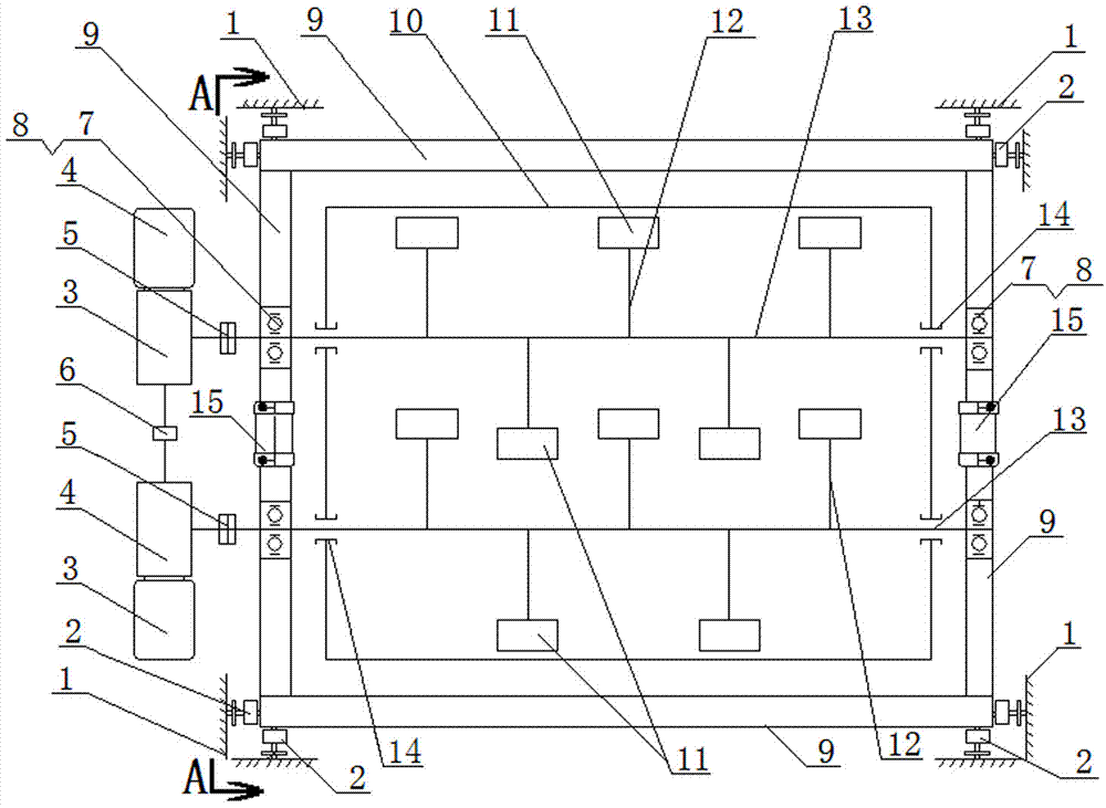
[0040] Figure 4 As shown, it is a top view structure schematic diagram of Embodiment 1 of the present invention, as can be seen from the figure, it is in figure 1 The front and rear beams in the square frame-shaped vibrating frame 9 are omitted on the basis of the above, and the left vibrating beam 16 and the right vibrating beam 17 are connected to the upper, lower, left, right, and outer sides of the two ends of the remaining left vibrating beam 16 and the right vibrating beam 17. with figure 1 The same constitutes a shaft vibrating forced mixer.

Embodiment 2

[0042] Figure 5 Shown, is the top view structural representation of embodiment 2 of the present invention; As can be seen from the figure, it is in Figure 4 On the basis of the left vibrating beam 16 and the buffer 2 connected to its two ends, and the two vertical vibrators 15 arranged on the left vibrating beam 16 are omitted; the bearing 8 at the left end of the two stirring shafts 13 passes through the bearing seat 7 It is fixedly connected with the fixed frame to form a shaft vibration forced mixer.

Embodiment 3

[0044] Image 6 Shown is a top view structural schematic diagram of Embodiment 3 of the present invention, Figure 7 yes Image 6 The enlarged schematic diagram of the right-view structure of ; from the two figures, it can be seen that Figure 4 The left vibrating beam 16 and the right vibrating beam 17 are omitted on the basis of the above; the buffer 2 is arranged on the bottom, left and right sides of the bearing housings 7 at both ends of the two stirring shafts 13 and is positioned and connected with the fixed frame 1, and each bearing housing 7 A vibrator 15 is horizontally arranged on the top of the shaft to form a shaft vibrating forced mixer.


PUM


Abstract

The invention discloses a shaft-vibration forced mixer. The shaft-vibration forced mixer comprises a mixing barrel, mixing shafts, a fixed frame, a speed reducer and a mixing motor. The shaft-vibration forced mixer is characterized by further comprising vibration frames horizontally arranged around the outer side of the mixing barrel, and two vibrators horizontally and vertically arranged on the vibration frames between bearing seats at the two ends of each of the two mixing shafts separately, wherein the two ends of each mixing shaft are fixedly connected with the corresponding vibration frame through the bearing seats and bearings thereof. The mixing shafts and mixing blades of the mixer rotate under the driving of the speed reducer and the mixing motor, and vibration is generated under the driving of the vibrators. A mixture can be adequately dispersed and uniformly fused, so that the mixture realizes macroscopic uniformity and microcosmic uniformity in a real sense; and repeated collision is carried out in the mixture to form high-quality cementing materials, and the cementing materials are uniformly distributed in the mixture and in better firm bonding with aggregates, so that a mixture with higher performance is formed. The shaft-vibration forced mixer is applicable to cement stabilized soil, cement concrete, cement mortar and asphalt mixture.

Description

technical field [0001] The invention relates to a mixing material mixing machine, especially a mixing machine and technology for cement stabilized soil, cement concrete, cement mortar and asphalt mixture. Background technique [0002] The function of the mixer is to mix the prepared various materials into a uniform mixture that meets the quality requirements. At present, the commonly used mixers are generally divided into self-falling mixers and forced mixers. The mixing modes of these two mixers are collectively called static mixing. The self-falling mixer uses the diverter plate inside the mixing drum to repeatedly lift, divide and drop the materials in the drum when it rotates, so that the materials are continuously dispersed and distributed to achieve the purpose of uniform mixing; the forced mixer uses rotating stirring The shaft and its blades shear, squeeze and stir the materials to make them tumbling, convection and other forced mixing, so that the materials are eve...

Claims


Application Information

Patent Timeline
IPC IPC(8): B28C5/48B28C5/14
CPCB28C5/147B28C5/148B28C5/48
Inventor 归立发
Owner 归立发
Why Eureka
Try Eureka