Method for bonding ZrO2 ceramic and metal

A metal connection and ceramic technology, applied in the field of heterogeneous material connection, can solve the problems of joint service temperature control, uncontrollable interface reaction, and easy breakdown of materials, and achieve the effects of low cost, shortened cycle, and increased service temperature

Active Publication Date: 2017-09-05
JILIN UNIV
View PDF6 Cites 5 Cited by
  • Summary
  • Abstract
  • Description
  • Claims
  • Application Information

AI Technical Summary

Problems solved by technology

[0005] The present invention will solve existing ZrO 2 When brazing ceramics and metals, it is necessary to use active solder or pre-metallize the surface of ceramics. The process is complex, and the service temperature of the joint is limited by the melting point of the solder, and the interface reaction is uncontrollable; the traditional diffusion connection requires high pressure and long time. , low efficiency; problems such as high voltage, high energy consumption, poor safety, and easy breakdown of materials during field diffusion connection, and a ZrO 2 Methods of joining ceramics to metals

Method used


Image

  • Method for bonding ZrO2 ceramic and metal
  • Method for bonding ZrO2 ceramic and metal
  • Method for bonding ZrO2 ceramic and metal

Examples


Embodiment 1

[0030] A kind of realization ZrO described in this embodiment 2 The new method of joining ceramics to metals proceeds as follows:

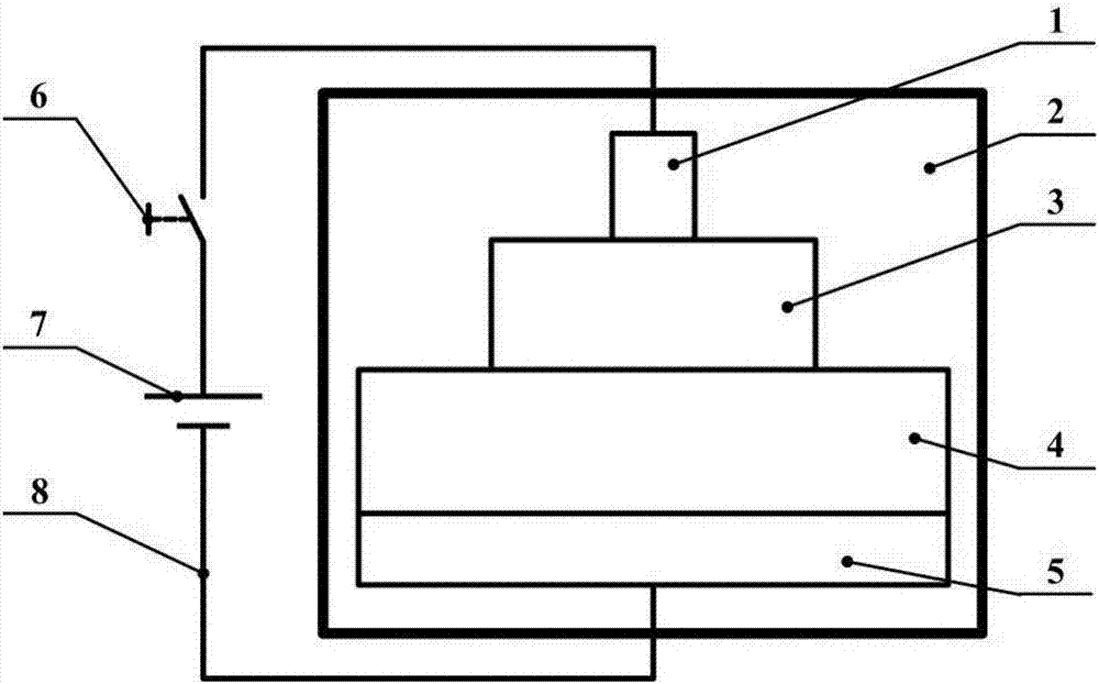
[0031] a. ZrO 2 The joint surface of ceramic and metal nickel was mechanically polished, then ultrasonically cleaned in acetone and dried, and then the ZrO 2 The ceramic 3 and the pure nickel 4 are stacked up and down, and placed on the graphite bottom electrode 5 in the high-temperature vacuum furnace;

[0032] The ZrO 2 Ceramics are doped with 3mol% Y 2 o 3 Stabilizer ZrO 2 For ceramics, the size is 8mm in diameter and 5mm in thickness, and the size of pure nickel is 20mm×20mm×5mm;

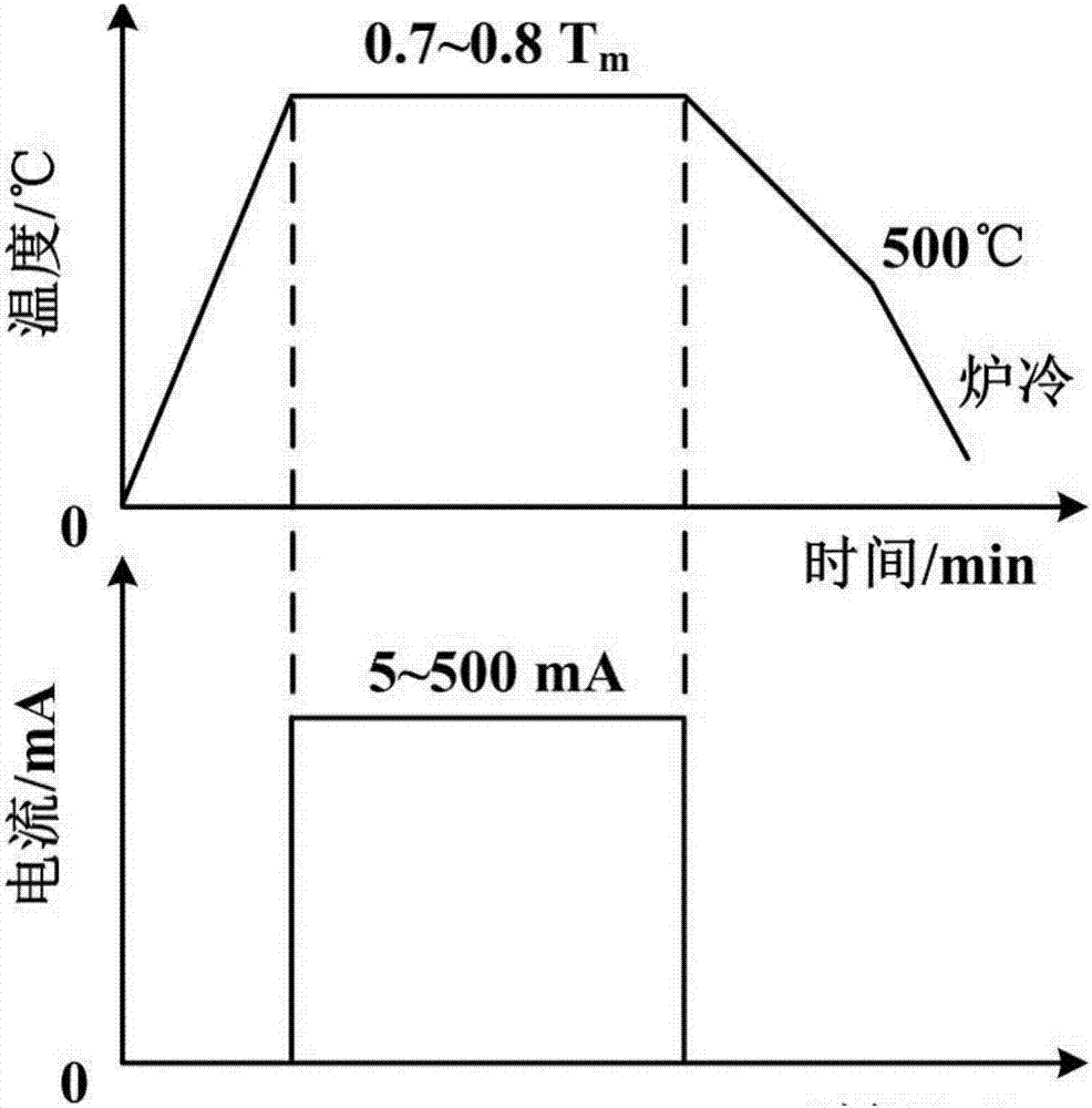
[0033] b. Vacuumize the vacuum furnace 2 until the vacuum enters 2×10 -3 After Pa, heat up to 1100°C at a rate of 20°C / min;

[0034] c. Unscrew the graphite upper electrode 1 to make it contact with ZrO 2 The upper surface contact of ceramic 3, the ZrO 2 The ceramic 3 is connected to the positive pole of the power supply 7, and the pure nickel 4 is connect...

Embodiment 2

[0039] The difference between this embodiment and Embodiment 1 is that the effective value of the constant current is 5mA, the power-on time is 60min, and other parameters and steps are the same as Embodiment 1. Measured Ni / ZrO 2 The shear strength of the joint is 124.8MPa, and the fracture of the joint is in Ni / ZrO 2 interface.

Embodiment 3

[0041] The difference between this embodiment and Embodiment 1 is that the effective value of the constant current is 500 mA, the power-on time is 5 minutes, and other parameters and steps are the same as those of Embodiment 1. Measured Ni / ZrO 2 The shear strength of the joint is 140.9MPa, and the fracture of the joint is in Ni / ZrO 2 interface.


PUM

PropertyMeasurementUnit
shear strengthaaaaaaaaaa

Abstract

The invention relates to a method for bonding a ZrO2 ceramic and a metal. The method comprises the following steps: superposing the ZrO2 ceramic and metal up and down without putting any solder in the middle, putting the ZrO2 ceramic and metal between the top and bottom electrodes in a high temperature vacuum furnace, heating to 0.7-0.8 time of the metal melting point temperature Tm, applying a 5-500mA constant direct current to the metal / ZrO2 ceramic by using the top and bottom electrodes, electrifying and keeping the temperature for 5-60 minutes, and cooling to room temperature, thereby completing the bonding between the ZrO2 ceramic and metal. Compared with the traditional metal-ceramic brazing, the method does not need the solder or need to perform pre-metallization treatment on the ceramic surface, so the technical process is simple and easy to implement. Compared with the traditional diffusion bonding, the method does not need high pressure, and has the advantage of shorter time. Compared with the field-induced diffusion bonding, the method has the advantages of low voltage, low energy consumption and higher operational safety in the bonding process, and thus, has obvious technical advantages.

Description

technical field [0001] The invention belongs to the technical field of connection of heterogeneous materials, in particular to a ZrO 2 Methods of joining ceramics to metals. Background technique [0002] ZrO 2 As an advanced structural ceramic, it has been widely used in thermal barrier coatings, thermal insulation layers of engine combustion chambers, and solid oxide fuel cells. However, the inherent brittleness of ceramics severely limits its application range. Metal and ceramics form an obvious complementary relationship in terms of performance. If the connection technology is used to combine the two, the excellent performance of each can be fully exerted, and components that meet the current harsh service environment requirements can be prepared. Cutting-edge fields such as nuclear energy show broad application prospects. [0003] Because the physical and chemical properties of ceramics and metals are quite different, it is difficult to realize the connection between...

Claims


Application Information

Patent Timeline
Patent Type & Authority Applications(China)
IPC IPC(8): C04B37/02
CPCC04B37/021C04B2237/348C04B2237/52
Inventor 沈平杨博于连腾郭瑞芬姜启川
Owner JILIN UNIV
Why Eureka
Try Eureka