Vapor chamber based on flat-plate loop heat pipe

A technology of soaking plate and heat pipe, which is used in circuits, indirect heat exchangers, lighting and heating equipment, etc., can solve problems such as increasing flow length, and achieve the effects of small flow resistance, improved heat transfer capacity, and reduced thickness

Active Publication Date: 2017-09-05
BEIJING INST OF SPACECRAFT SYST ENG
View PDF5 Cites 6 Cited by
  • Summary
  • Abstract
  • Description
  • Claims
  • Application Information

AI Technical Summary

Problems solved by technology

[0008] However, the application of vapor chambers has the following problems: there are contradictions in the requirements for product performance improvement on the capillary core. Heat transfer capacity, increase limit heat flux density, increase anti-overload and anti-gravity working ability, increase vapor chamber size; on the other hand, in order to improve some p

Method used


Image

  • Vapor chamber based on flat-plate loop heat pipe
  • Vapor chamber based on flat-plate loop heat pipe
  • Vapor chamber based on flat-plate loop heat pipe

Examples


Embodiment 1

[0026] Example 1: Thermal conduction vapor chamber

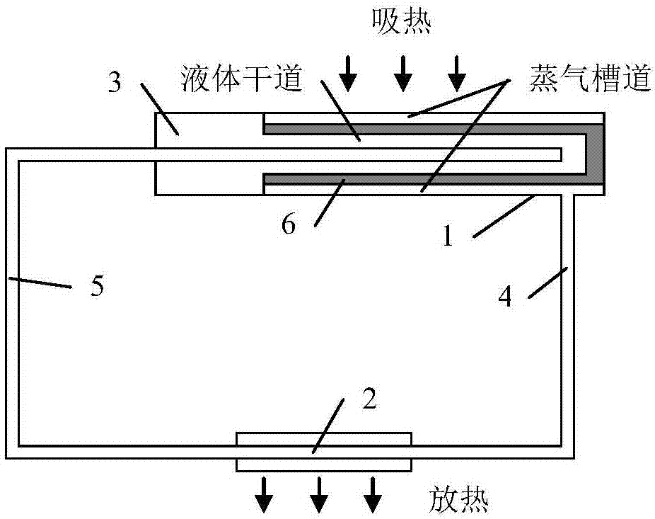
[0027] Such as Figure 4-Figure 5 As shown, the flat loop heat pipe composed of the evaporator, the liquid reservoir and the gas / liquid pipeline is pre-embedded in the aluminum alloy heat spreader by gluing or welding to form a vapor chamber based on the flat loop heat pipe. The vapor chamber is installed in close contact with the circuit board to be dissipated, so that the evaporator of the flat-plate loop heat pipe is arranged in the area where the vapor chamber and the largest heat source of the circuit board (that is, the position with the largest heat generation of the circuit board) are attached, and the evaporator The side with the steam channel fits the largest heat source. The evaporator can be pre-buried in the aluminum alloy heating plate, or only fixed in the aluminum alloy heating plate, and the evaporator is exposed and directly attached to the largest heat source. The liquid reservoir of the flat-plate loop ...

Embodiment 2

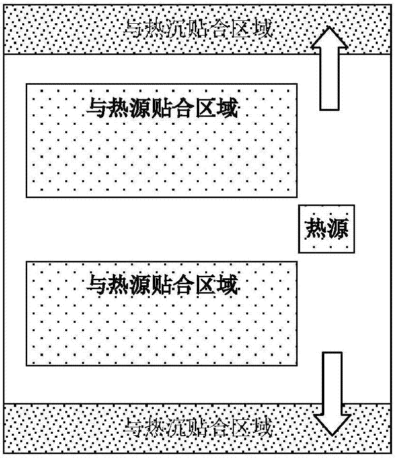
[0029] Example 2: Expansion vapor chamber

[0030] The main difference from the thermal conduction vapor chamber is that, except for the "area that fits with the heat source", the other areas on the vapor chamber that are not in contact with the heat source are regarded as the "area that fits with the heat sink". Therefore, the gas / liquid pipeline is reciprocally arranged between the "area attached to the heat source" and other areas. It works on the same principle as a thermally conductive vapor chamber.


PUM


Abstract

The invention discloses a vapor chamber based on a flat-plate loop heat pipe. The heat transfer capability, the limiting heat flow density heat dissipation capability, the anti-overloading and inverse gravity capability of the vapor chamber are improved. The size of the vapor chamber is increased. The thickness of the vapor chamber is reduced. The conflicting requirements of performance improvement of the vapor chamber for both large pore size of capillary wick and small pore size of the capillary wick are met. The flat-plate loop heat pipe composed of an evaporator, a liquid accumulator and a gas/liquid pipe is pre-embedded in an aluminum alloy plate to form the vapor chamber based on the flat-plate loop heat pipe. The evaporator of the flat-plate loop heat pipe is arranged in the region, which is attached to a biggest heat source of a chip to be cooled, of the vapor chamber. The side, provided with a vapor channel, of the evaporator is attached to the biggest heat source. The vapor chamber is provided with a heat sink attached region and a heat source attached region. The gas/liquid pipe is led out of an outlet of the evaporator and is arranged in the heat sink attached region and the heat source attached region in a reciprocating mode, finally passes the heat sink attached region and returns to the liquid accumulator of the flat-plate loop heat pipe.

Description

technical field [0001] The invention relates to a soaking plate, in particular to a soaking plate based on a flat loop heat pipe, which belongs to the technical field of heat dissipation of electronic equipment. Background technique [0002] The loop heat pipe is a high-efficiency two-phase heat transfer device, which has the characteristics of high heat transfer performance, long-distance heat transfer, excellent temperature control characteristics, arbitrary bending of the pipeline, and convenient installation. With comparable advantages, the loop heat pipe has very broad application prospects in many fields such as aviation, aerospace, and ground electronic equipment heat dissipation. [0003] Such as figure 1 As shown, the loop heat pipe mainly includes: an evaporator 1, a condenser 2, a liquid receiver 3, a vapor pipeline 4 and a liquid pipeline 5. Evaporation, absorbing the heat outside the evaporator 1, the generated steam flows from the steam pipeline 4 to the cond...

Claims


Application Information

Patent Timeline
IPC IPC(8): F28D15/04
CPCF28D15/04F28D15/043F28D15/046F28D15/0233F28D15/0266H01L23/427
Inventor 张红星满广龙黄金印李国广
Owner BEIJING INST OF SPACECRAFT SYST ENG
Why Eureka
Try Eureka