Hydraulic watertight door control system and method for vessel

A control system and watertight door technology, applied in general control system, control/regulation system, program control, etc., can solve the problems of no fault diagnosis, poor reliability, and large PLC module size, etc., to achieve convenient replacement and maintenance, high reliability , extended and flexible effects

Pending Publication Date: 2017-09-05
WUXI HAIHE EQUIP TECH CO LTD
View PDF8 Cites 0 Cited by
  • Summary
  • Abstract
  • Description
  • Claims
  • Application Information

AI Technical Summary

Problems solved by technology

[0004] At present, the existing hydraulic watertight door control systems are mostly controlled by relays, PLCs or single-chip microcomputers; among them, the hydraulic watertight doors controlled by relays are relatively low-end, relying on relays to achieve logic control, with many wiring and no fault diagnosis function, they are already facing elimination; PLC is used The cost of the controlled hydraulic watertight door is relatively high, and due to the large size of the PLC module, the control box used in the control system is also relatively large, occupying more space in the bulkhead; the hydraulic watertight door controlled by a single-chip computer is less flexible, and the control and indication The circuit is not separated and cannot meet the requirements of the specification. At present, there is no report on the hydraulic watertight door control system controlled by an independent single-chip microcomputer for control and indication.
In short, the existing marine hydraulic watertight door control system has problems such as insufficient flexibility and poor reliability.
[0005] Current patent: An electrical control device and method for a marine hydraulic watertight door, CN 102945036A, which is controlled by a single-chip microcomputer, and uses a main module plus an expansion module to solve the problem of poor flexibility, but once the main module fails, it will cause the entire ship. The watertight door is out of control, a huge safety hazard, and does not meet the requirements of the classification society

Method used


Image

  • Hydraulic watertight door control system and method for vessel
  • Hydraulic watertight door control system and method for vessel
  • Hydraulic watertight door control system and method for vessel

Examples


Embodiment Construction

[0040] The specific embodiments of the present invention will be further described below in conjunction with the accompanying drawings.

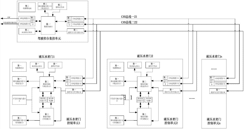
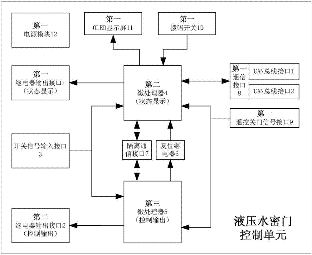
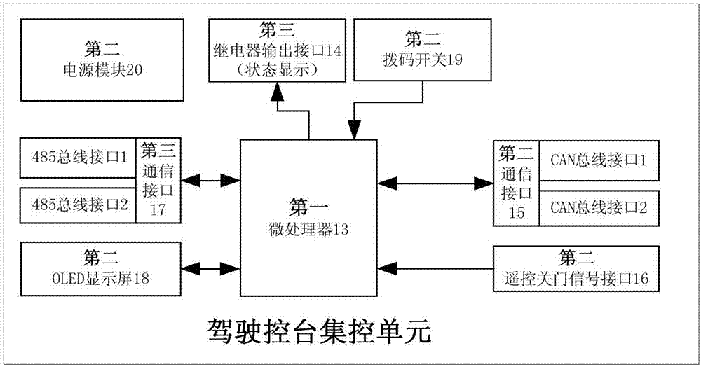
[0041] Figure 1~3 Including the first relay output interface 1, the second relay output interface 2, the switch signal input interface 3, the second microprocessor 4, the third microprocessor 5, the reset relay 6, the isolation communication interface 7, the first communication interface 8. The first remote control door closing signal interface 9, the first dial switch 10, the first OLED display screen 11, the first power module 12, the first microprocessor 13, the third relay output interface 14, the second communication interface 15, The second remote control door closing signal interface 16, the third communication interface 17, the second OLED display screen 18, the second dial switch 19, the second power module 20, CAN bus one 21 and CAN bus two 22, etc.

[0042] Such as Figure 1~3 As shown, the present invention is a marine hydraul...


PUM


Abstract

The invention belongs to the technical field of marine hydraulic watertight door control, and relates to a hydraulic watertight door control system for a vessel. The system is composed of two parts: a bridge control unit and a hydraulic watertight door control unit. In use, each hydraulic watertight door is equipped with one hydraulic watertight door control unit, and the number of the hydraulic watertight door control units depends on the number of the hydraulic watertight doors, and then the hydraulic watertight door control unit and the hydraulic watertight door are both controlled by a bridge centralized control unit. As shown in Figure 1, the bridge centralized control unit and the hydraulic watertight door control unit are connected through two independent CAN buses, when one CAN bus breaks down, the other CAN bus can guarantee normal communication. The control device can flexibly achieve the hardware system configuration based on the number of the controlled hydraulic watertight doors, each hydraulic watertight door is controlled by using an independent control unit, and each control unit is provided with two independent microprocessors, thus the safety of vessel navigation is greatly increased.

Description

technical field [0001] The invention belongs to the technical field of marine hydraulic watertight door control, and relates to a marine hydraulic watertight door control system and method. Background technique [0002] The watertight door of a ship is one of the important equipment to ensure the safety of the ship's navigation. Once the hull part is broken, the watertight door in the closed state can resist the immersion of the hull outside the broken section and prevent the ship from sinking. [0003] The forms of marine watertight doors mainly include sliding type, hinged type and rolling type. According to the driving form, they can be divided into manual, electric, electro-hydraulic and other forms. The present invention is mainly aimed at the control system of the marine electro-hydraulic drive sliding watertight door, hereinafter referred to as the hydraulic watertight door. [0004] At present, the existing hydraulic watertight door control systems are mostly contro...

Claims


Application Information

Patent Timeline
Patent Type & Authority Applications(China)
IPC IPC(8): G05B19/418G05B19/042G05B19/048
CPCG05B19/0421G05B19/0428G05B19/048G05B19/4186G05B19/4188G05B19/4189G05B2219/24024G05B2219/2214G05B2219/25176G05B2219/25032G05B2219/2637G05B2219/25338
Inventor 蒋恒深潘道元吴朋朋丁平黄浩刘欢
Owner WUXI HAIHE EQUIP TECH CO LTD
Why Eureka
Try Eureka