A grid driving unit, a row grid scanning driver, a driving method of a grid driving unit and a driving method of a row grid scanning driver

A gate drive and row gate technology, applied to instruments, static indicators, etc., can solve problems such as failure to make good use of screen symmetry, failure to work normally, and complex circuit structure

Active Publication Date: 2017-09-05
SOUTH CHINA UNIV OF TECH
View PDF10 Cites 3 Cited by
  • Summary
  • Abstract
  • Description
  • Claims
  • Application Information

AI Technical Summary

Problems solved by technology

[0003] The new oxide thin film transistor device has become a popular research object in recent years because of its excellent performance and simple manufacturing process. However, the oxide thin film transistor is an N-type device and has the characteristics of negative threshold voltage. The line scanning circuit developed by the transistor will cause a sharp increase in power consumption of the circuit or even fail to work properly because the oxide thin film transistor cannot be completely turned off.
In order to completely turn off the oxide thin film transistor, most of the new line scan driving circuits will use two or more negative power supplies inside, but multiple negative power supplies will make the circuit structure more complicated, the internal wiring will increase, and the circuit area will be reduced. increases, and the requirements for each power supply are also more stringent
In addition, most line scanners use a single-side drive architecture, so that the line integrated circuits can only be concentrated on one side of the screen, which fails to make good use of the symmetry of the screen, resulting in waste of space and does not meet people's aesthetic needs for narrow borders

Method used


Image

  • A grid driving unit, a row grid scanning driver, a driving method of a grid driving unit and a driving method of a row grid scanning driver
  • A grid driving unit, a row grid scanning driver, a driving method of a grid driving unit and a driving method of a row grid scanning driver
  • A grid driving unit, a row grid scanning driver, a driving method of a grid driving unit and a driving method of a row grid scanning driver

Examples


Embodiment

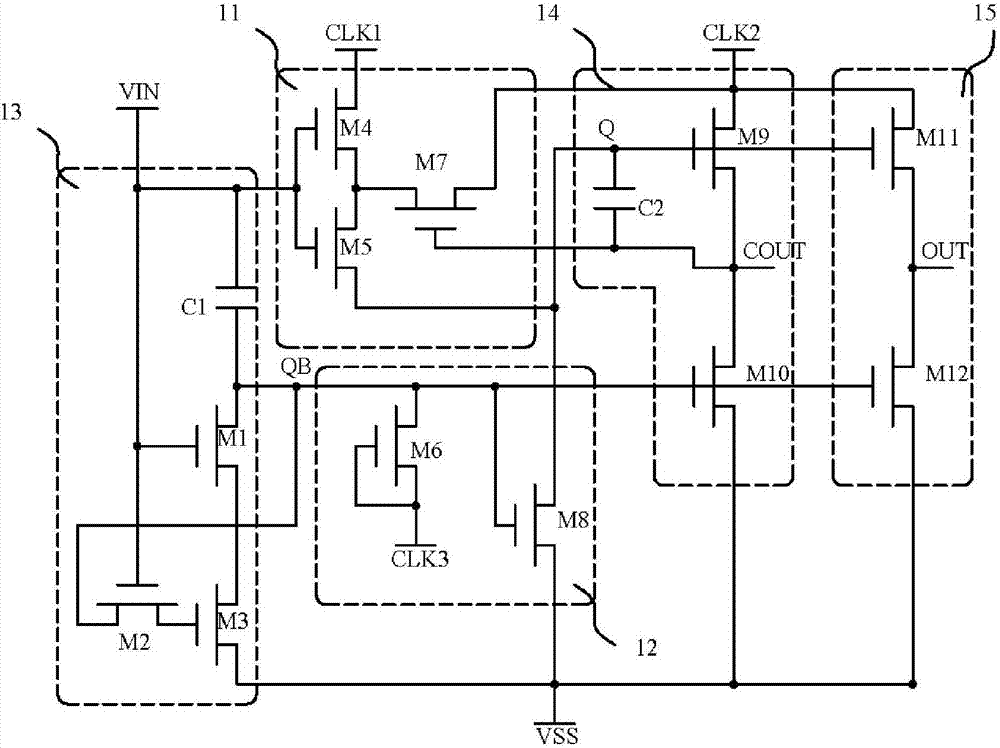
[0048] Such as figure 1 As shown, a gate drive unit is characterized in that it is composed of a signal input module 11, a negative pressure module 13, an inverter module 12, a cascaded output module 14, and a scan output module 15. The gate drive unit The control signal includes a first clock input port CLK1, a second clock input port CLK2, a third clock input port CLK3, a first power supply port VSS, a signal input port VIN, a first output port COUT and a second output port OUT;

[0049] The signal input module is composed of a fourth transistor M4, a fifth transistor M5, and a seventh transistor M7. The gates of the fourth transistor M4 and the fifth transistor M5 are connected to the signal input port VIN, and the drain of the fourth transistor M4 is connected to the fourth transistor M4. A clock input port CLK1 is connected, and its source is respectively connected to the drain of the fifth transistor M5 and the source of the seventh transistor M7, and the source of the f...


PUM


Abstract

The invention discloses a grid driving unit, a row grid scanning driver, a driving method of a grid driving unit and a driving method of a row grid scanning driver. The grid driving unit comprises a signal input module, a negative pressure module, an inverter module, a cascade output module, and a scanning output module. Through the negative pressure module, the grid driving unit can function normally only through a single negative power supply, so requirements of the design of an external circuit are reduced, the structure of the circuit is simplified, the amplitude of circuit level is reduced, and power consumption of the circuit is reduced. Meanwhile, the circuit adopts a double-side driving configuration, so aesthetic demands of a narrow frame can be realized. Multiple grid driving units are connected in series and are connected with corresponding driving time sequences to form the row grid scanning driver, a single-side driver needs three driving clock signals, a two-side driver needs six driving clock signals, streamline type driving time sequences are adopted, and duty ratios are all 16.7%. Grid voltages are increased through capacitance coupling in the cascade output module, and in the negative pressure module, negative pressure attenuation characteristics facilitate applications in high-resolution display.

Description

technical field [0001] The invention relates to the field of row grid scanning of an active matrix light-emitting flat panel display, in particular to a grid driving unit, a row grid scanning driver and a driving method thereof. Background technique [0002] The traditional display panel row gate drive circuit requires a special drive chip, and the chip is crimped on the glass substrate to drive the pixel circuit through the process. In recent years, with the development of technology, the row integration technology, which uses thin film transistors to directly integrate row gate drive circuits in display panels instead of driver chips, has become a hot topic in current research. In line integration technology, the gate drive circuit and the pixel circuit are integrated in the same array, which can avoid the timing disorder caused by the difference in signal trace length through layout and wiring, and improve the signal quality; it can also reduce the substrate area and proc...

Claims


Application Information

Patent Timeline
Patent Type & Authority Applications(China)
IPC IPC(8): G09G3/20
CPCG09G3/20G09G2310/0267
Inventor 吴为敬陈俊伟宁洪龙徐苗王磊彭俊彪
Owner SOUTH CHINA UNIV OF TECH
Why Eureka
Try Eureka