Glass fiber cloth gluing device

A technology of glass fiber cloth and glue, which is applied to the device for coating liquid on the surface, pretreatment of the surface, coating, etc. It can solve the problems of affecting the quality of gluing, hindering the adhesion of glue, and affecting the purity of glue, etc., to achieve Improved gluing quality, simple structure and good working stability

Active Publication Date: 2017-09-12
浙江凯澳新材料有限公司
View PDF7 Cites 2 Cited by
  • Summary
  • Abstract
  • Description
  • Claims
  • Application Information

AI Technical Summary

Problems solved by technology

But this equipment has a shortcoming: in actual processing, some dust will inevitably adhere to the fabric, and this equipment is not equipped with a dust removal structure, which will cause the dust to contact with the glue, which will not only affect the purity of the glue, but also prevent the glue from adhering to the fabric on, ultimately affecting the quality of the entire gluing

Method used


Image

  • Glass fiber cloth gluing device
  • Glass fiber cloth gluing device
  • Glass fiber cloth gluing device

Examples


Embodiment 1

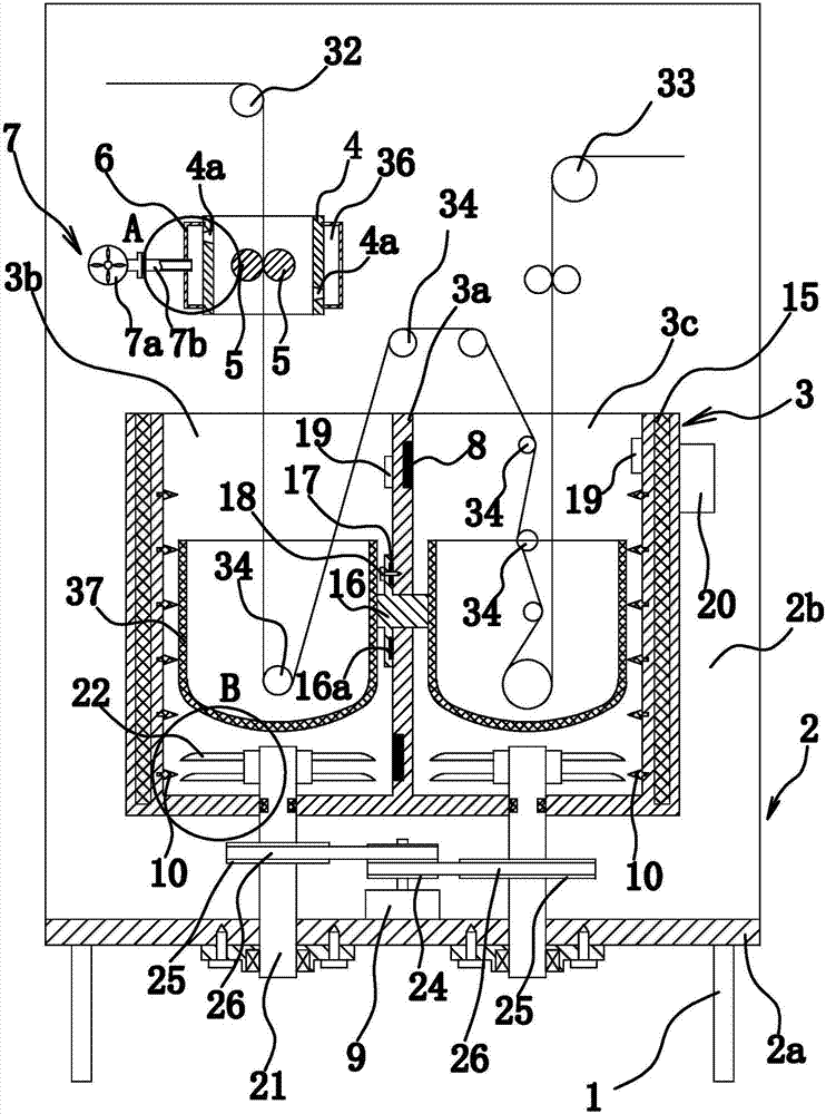
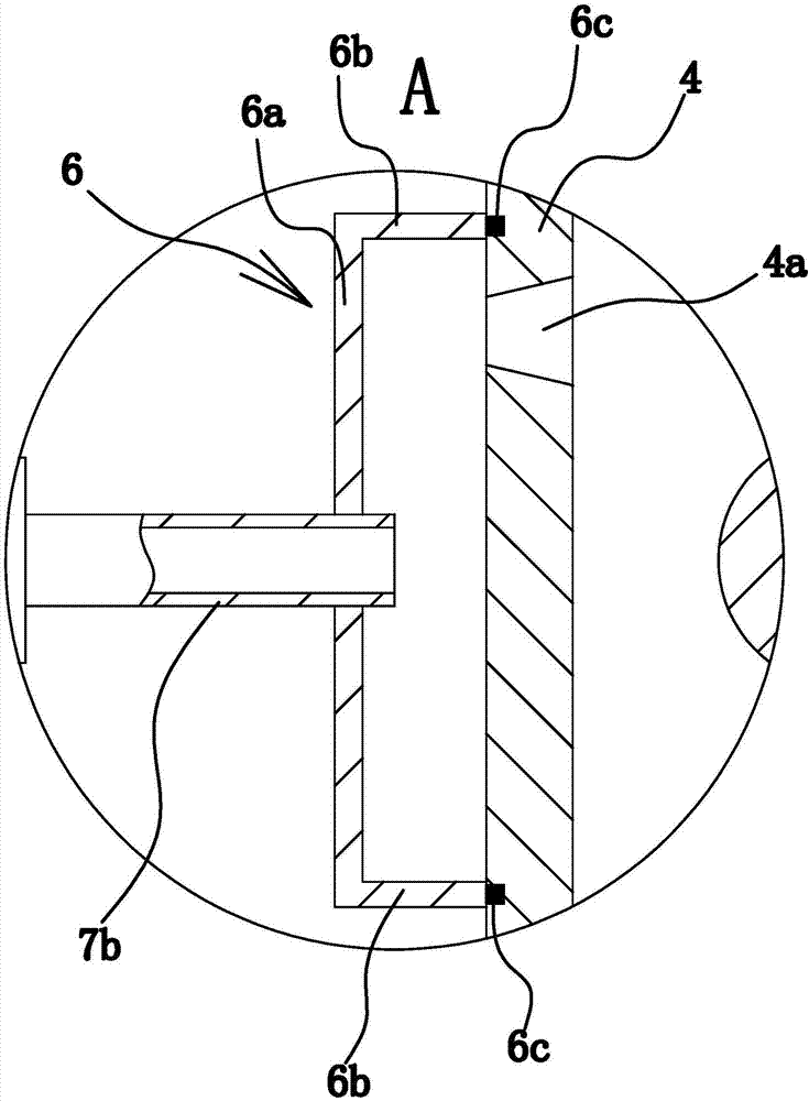
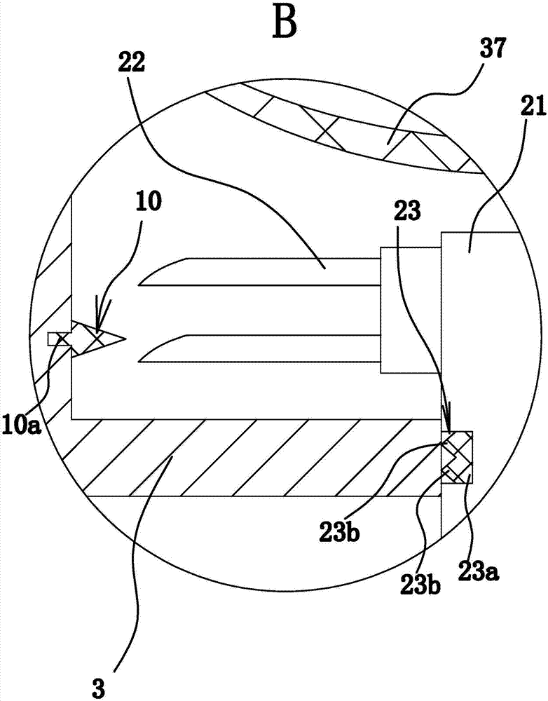
[0068] like Figure 1 to Figure 6 As shown, the glass fiber cloth gluing device consists of a bracket 1, a workbench 2, a tank body 3, an air suction ring 4, a roller shaft 5, a sealing ring 6, a negative pressure piece 7, an electric heating plate 8, a motor 9, and a crushing head 10. Composition of support block 11, piston 12, push plate 13, spring 14, etc. Wherein, the electric heating plate 8 is an existing product, which can be bought in the market.

[0069] Specifically, the workbench 2 is located on the support 1, such as figure 1 As shown, the workbench 2 is L-shaped, and the workbench 2 includes a horizontally arranged support part 2a and a vertically arranged support part 2b. Both the support part 2a and the support part 2b are plate-shaped, and the support part 1 2a is fixed to the bracket 1 by welding.

[0070] The tank body 3 is arranged on the front side of the workbench 2, and the notch of the tank body 3 faces upward. The tank body 3 and the supporting port...

Embodiment 2

[0095] The structure and principle of this second embodiment are basically the same as that of the first embodiment. The difference is that the sealing structure includes an annular groove arranged on the side wall of the connecting rod 16, and a sealing ring 2 is arranged in the annular groove, and the sealing ring The outer wall of the second is closely against the hole wall of the mounting hole.

Embodiment 3

[0097] The structure and principle of the present embodiment three are basically the same as those of the first embodiment, except that the motor 9 is located between the two stirring shafts 21, and the transmission mechanism includes a main gear fixed on the main shaft of the motor 9 and fixed on the two stirring shafts respectively. Two secondary gears on the 21, and both secondary gears are meshed with the main gear.


PUM


Abstract

The invention provides a glass fiber cloth gluing device and belongs to the technical field of machines. The problem that existing gluing devices are poor in quality is solved through the glass fiber cloth gluing device. The glass fiber cloth gluing device comprises a bracket and a workbench fixed to the bracket. A first glue solution tank and a second glue solution tank are parallelly fixed to the workbench. The workbench is further provided with a cloth guiding mechanism. An air suction ring allowing glass fiber cloth to penetrate through is arranged over the first glue solution tank and fixed to the workbench. Roller shafts are rotationally installed in the air suction ring. The number of the roller shafts is two, and the roller shafts are parallel. A clamping opening is formed between the two roller shafts. A sealing ring is arranged and fixed outside the air suction ring in a sleeving mode. An annular dust removing cavity of a closed structure is formed between the air suction ring and the sealing ring. The air suction ring is provided with dust collection openings enabling an inner cavity of the air suction ring to communicate with the dust removing cavity. The number of the dust collection openings is two. The glass fiber cloth gluing device further comprises a negative pressure piece which can form negative pressure in the dust removing cavity. The glass fiber cloth gluing device has the advantage of being good in quality.

Description

technical field [0001] The invention belongs to the technical field of machinery, and relates to a gluing device, in particular to a glass fiber cloth gluing device. Background technique [0002] Glass fiber is an inorganic non-metallic material with excellent performance. It has various types and has the advantages of good insulation, strong heat resistance, good corrosion resistance and high mechanical strength. [0003] The gluing process of glass fiber cloth is an important step in the processing of glass fiber cloth, and this process needs to be used in conjunction with the gluing device. Existing gluing devices such as the gluing equipment for glass fiber cloth disclosed in the Chinese Patent Library [Application No.: 201020597158.9; Authorized Announcement No.: CN 201864943 U] include a first accommodating groove to define a first accommodating space. to accommodate the first glue; a first roller, at least a part of which is located in the first accommodation space; ...

Claims


Application Information

Patent Timeline
Patent Type & Authority Applications(China)
IPC IPC(8): B05C3/12B05D3/00B05C13/02B05C11/11B05C11/10B05C3/04
CPCB05C3/005B05C3/04B05C3/125B05C11/1026B05C11/11B05C13/02B05D3/002
Inventor 沈海平
Owner 浙江凯澳新材料有限公司
Why Eureka
Try Eureka