
Heating pipe network with intelligent online monitoring system

A technology of heating pipe network and monitoring system, which is applied in household heating, heating system, space heating and ventilation, etc. It can solve problems such as equipment noise, thermal imbalance, and scattered locations, so as to achieve reasonable setting and maintain thermal imbalance Effect

Inactive Publication Date: 2017-09-12
TIANJIN JINAN THERMAL POWER
View PDF0 Cites 8 Cited by
  • Summary
  • Abstract
  • Description
  • Claims
  • Application Information

AI Technical Summary

Problems solved by technology

There are many heat pump stations, heat exchange stations, and pump rooms under the heating center. Due to the scattered locations, most of them adopt manual monitoring, resulting in insufficient on-duty personnel and untimely maintenance.
Therefore, maintenance only depends on telephone scheduling, and it is difficult for the heating center to grasp the actual operation of the equipment, and it is impossible to achieve reasonable scheduling. On the one hand, it is a waste of manpower;
At the same time, each heat exchange station operates independently, it is difficult to achieve the overall best state of the heating system, and it is easy to cause thermal imbalance, affect the heating effect and cause a great waste of energy
Although individual cities have installed pressure and flow online detectors at each control point of the heating pipe network, this is not enough to solve the problems of unstable operation of the equipment in the station, equipment noise, excessive energy consumption, abnormal temperature and humidity in the station environment, etc.

Method used

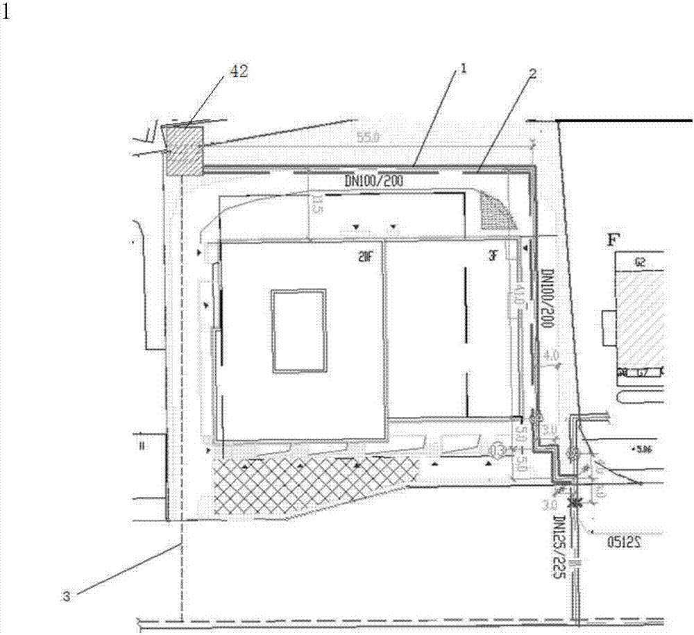
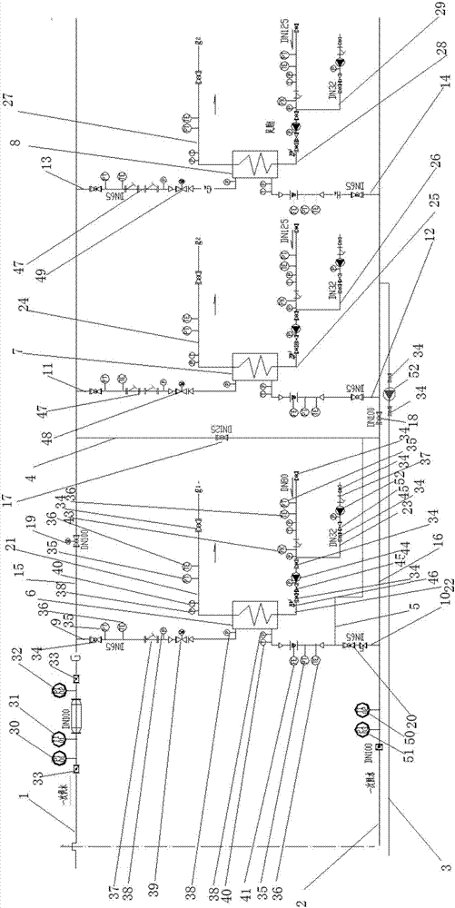

Image

  • Heating pipe network with intelligent online monitoring system
  • Heating pipe network with intelligent online monitoring system
  • Heating pipe network with intelligent online monitoring system

Examples


Embodiment 1

[0071] Embodiment 1: The renovation area is selected as a residence in 2012, with a construction area of ​​about 20,000 square meters. The heat exchange station includes a radiator unit and two floor heating units)

[0072] heating area

23435㎡

Number of heating households

210 households

Operation time

2012

Envelope Type

Three steps to save energy

[0073] load design

[0074] System design parameter table

[0075]

[0076] (1) The civil design thermal index of this heat exchange station is calculated and selected according to 50W, and the public building design thermal index is calculated and selected according to 70W. According to the characteristics of floor heating energy saving and low-temperature heat source heating, and the pilot station is a three-step energy-saving house, the primary side can meet the requirements according to 45W, and the corresponding equipment on the secondary side will not be changed.

[0077] (2) T...


PUM

PropertyMeasurementUnit
Nominal diameteraaaaaaaaaa

Abstract

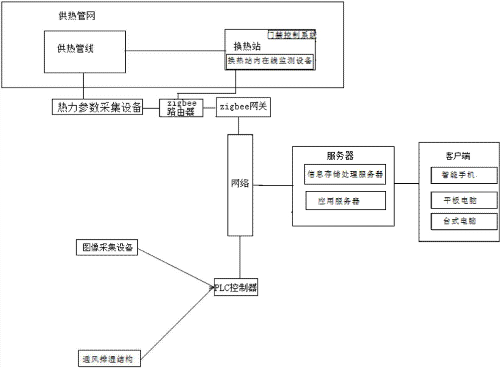
The invention belongs to the field of central heating and particularly relates to a heating pipe network with an intelligent online monitoring system. The heating pipe network with the intelligent online monitoring system comprises a heating pipe network and the online monitoring system. The intelligent online monitoring system comprises an online monitoring device in a heat exchange station, a thermal parameter collecting device, a zigbee router, a zigbee gateway, a network, a server, an image collecting device, an entrance guard control system, a ventilation and dehumidifying structure, a PLC and a client terminal. The online monitoring device in the heat exchange station comprises an intelligent electricity use information measuring and controlling terminal, a motor vibrating and shaft temperature sensor, a wireless noise sensor, a wireless temperature and humidity sensor and a wireless water sensor. The server comprises an information storage processing server and an application server. The heating pipe network with the intelligent online monitoring system has the beneficial effects that arrangement is reasonable, thermal parameters and environmental parameters in the heat exchange station are collected, the overall heating system is adjusted to be in the best state through the PLC, the thermal balance is kept, the heating effect is guaranteed, and energy waste is reduced.

Description

technical field [0001] The invention belongs to the field of central heating utilization, in particular to a heating pipe network with an intelligent online monitoring system. Background technique [0002] With the country's emphasis on environmental protection, urban central heating has become the mainstream. There are many heat pump stations, heat exchange stations, and pump rooms under the heating center. Due to the scattered locations, most of them adopt manual monitoring, resulting in insufficient on-duty personnel and untimely maintenance. Therefore, maintenance only depends on telephone scheduling, and it is difficult for the heating center to grasp the actual operation of the equipment, and it is impossible to achieve reasonable scheduling. On the one hand, it is a waste of manpower. At the same time, each heat exchange station operates independently, which makes it difficult to achieve the overall optimal state of the heating system, which may easily cause thermal ...

Claims


Application Information

Patent Timeline
IPC IPC(8): F24D3/10F24D19/10
CPCF24D3/10F24D19/1009
Inventor 杨洪健王健郭磊宏范皓郝圣楠雷春鸣
Owner TIANJIN JINAN THERMAL POWER
Learn More