Check patentability & draft patents in minutes with Patsnap Eureka AI!

Method and device for friction stir welding (FSW) assisted by additional heat source

A friction welding and auxiliary stirring technology, applied in welding equipment, non-electric welding equipment, metal processing equipment, etc., can solve the problems of high temperature strength limitation of stirring head, high welding cost, low life of stirring head, etc., so as to reduce welding cost and improve The effect of stirring needle life and simple structure

Active Publication Date: 2017-09-15
SHANDONG UNIV
View PDF7 Cites 9 Cited by
  • Summary
  • Abstract
  • Description
  • Claims
  • Application Information

AI Technical Summary

Problems solved by technology

However, there are still many problems to be solved in the friction stir welding technology research of high melting point materials such as steel, titanium alloy and nickel-based alloy. The main problem is the limitation of the high temperature strength of the stirring head, which makes the life of the stirring head low and the welding cost is high

Method used


Image

  • Method and device for friction stir welding (FSW) assisted by additional heat source
  • Method and device for friction stir welding (FSW) assisted by additional heat source
  • Method and device for friction stir welding (FSW) assisted by additional heat source

Examples


Embodiment 1

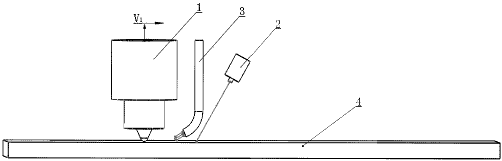
[0056] The additional heat source is laser: the material to be welded is butt joint of No. 45 steel plate with a thickness of 3 mm. Along the welding direction, there are stirring head, gas protection device, and laser beam output focusing lens. The distance between the gas protection nozzle and the edge of the shaft shoulder is 10 mm, along the horizontal direction The included angle is 45°, and the protective gas is argon. The angle that the stirring head deviates from the vertical direction along the welding direction is 2°. When the low-power laser is calibrated, the position where the beam irradiates on the upper surface of the workpiece is the center of the weld seam, the angle between the laser beam and the horizontal direction is 80°, and the laser beam irradiates The connection position of the plate is 2mm away from both ends of the plate, the diameters of the shaft shoulder and the stirring needle are 20mm and 8mm respectively, and the length of the stirring needle is...

Embodiment 2

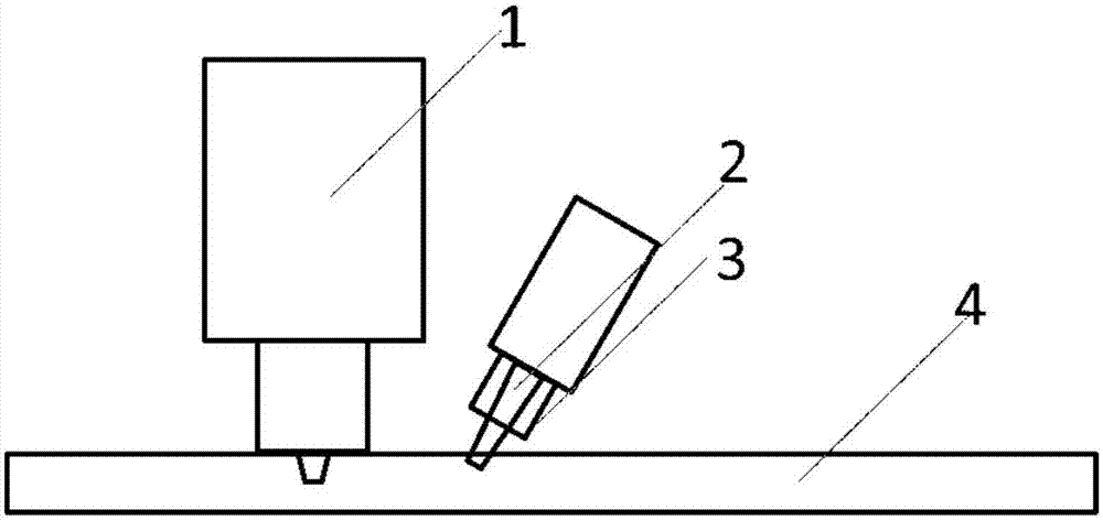
[0058] The additional heat source is electric arc: the material to be welded is 304 stainless steel plate with a thickness of 3mm butt joint, along the welding direction, there are stirring head, TIG arc, and gas protection device in sequence. The distance between the gas protection nozzle and the edge of the shaft shoulder is 10mm, and the angle along the horizontal direction is 45°, and the protective gas is a mixture of argon and helium. The angle at which the stirring head deviates from the vertical direction along the welding direction is 2°. The heating position of the TIG arc on the upper surface of the workpiece is the center of the weld seam. The angle between the TIG arc and the horizontal direction is 85°. Each end is 3mm, the diameter of the shaft shoulder and the stirring needle is 20mm and 8mm respectively, the length of the stirring needle is 2.9mm, during the welding process, the axial downward pressure is 3000kN, the rotation speed of the stirring needle is 600...


PUM

PropertyMeasurementUnit
Diameteraaaaaaaaaa

Abstract

The invention discloses a method and a device for friction stir welding (FSW) assisted by an additional heat source and solves the problems of high FSW cost for high-melting-point materials such as steel, nickel-based alloys, titanium alloys and the like and short life of stir heads in the prior art. With the method and the device, a to-be-welded area reaches the semi-solid or superplastic state, so that rheology resistance of the high-melting-point materials can be substantially reduced, the welding moment can be reduced, the requirements for the performance of a stir head can be reduced, then abrasions of the stir head can be reduced, and the service life of a stir needle can be prolonged. According to the technical scheme, the device comprises the stir head for welding, an additional heat source component and a gas shielding device; the stir head is rotationally inserted into a butt weld or an overlapping weld of a workpiece and can move; the additional heat source component is used for providing heat for the workpiece to form an additional heat source heating area on the surface of the workpiece, is arranged in front of the stir head and is spaced from the stir head by the set distance; and the gas shielding device is located above the additional heat source heating area and / or in front of the stir head.

Description

technical field [0001] The invention relates to the field of welding, in particular to a friction stir welding method and device assisted by an additional heat source. Background technique [0002] Friction Stir Welding (FSW for short) is a solid-phase welding technology invented by The Welding Institute in 1991. Compared with traditional fusion welding, friction stir welding has obvious advantages such as fewer joint defects, high quality, small deformation, green welding process, and no pollution. The field has broad application prospects. Friction stir welding uses frictional heat and plastic deformation heat as the welding heat source. A columnar or threaded stirring needle is inserted into the workpiece to be welded. Through the high-speed rotation of the stirring needle, it rubs against the welding workpiece material. Heat is generated, which in turn heats up the material at the joint to reach a high-temperature plastic state. During the welding process, the frictio...

Claims


Application Information

Patent Timeline
IPC IPC(8): B23K20/12B23K20/14B23K20/26
CPCB23K20/122B23K20/1275B23K20/14B23K20/26
Inventor 秦国梁江海红敖志勇周军
Owner SHANDONG UNIV
Features
  • R&D
  • Intellectual Property
  • Life Sciences
  • Materials
  • Tech Scout
  • Unparalleled Data Quality
  • Higher Quality Content
  • 60% Fewer Hallucinations
Learn More