
Method for manufacturing bearing assemblies

A technology of bearing components and bearings, which is applied to the rigid support of bearing components, bearing assembly, bearing components, etc., can solve the problems of time-consuming and high cost, and achieve the effect of simplifying the manufacturing process

Active Publication Date: 2017-09-15
MAHLE INT GMBH
View PDF7 Cites 0 Cited by
  • Summary
  • Abstract
  • Description
  • Claims
  • Application Information

AI Technical Summary

Problems solved by technology

However, these cages have to be manually tightened laboriously and loosened again after the actual grinding process, which is time consuming and expensive

Method used


Image

  • Method for manufacturing bearing assemblies
  • Method for manufacturing bearing assemblies
  • Method for manufacturing bearing assemblies

Examples


Embodiment Construction

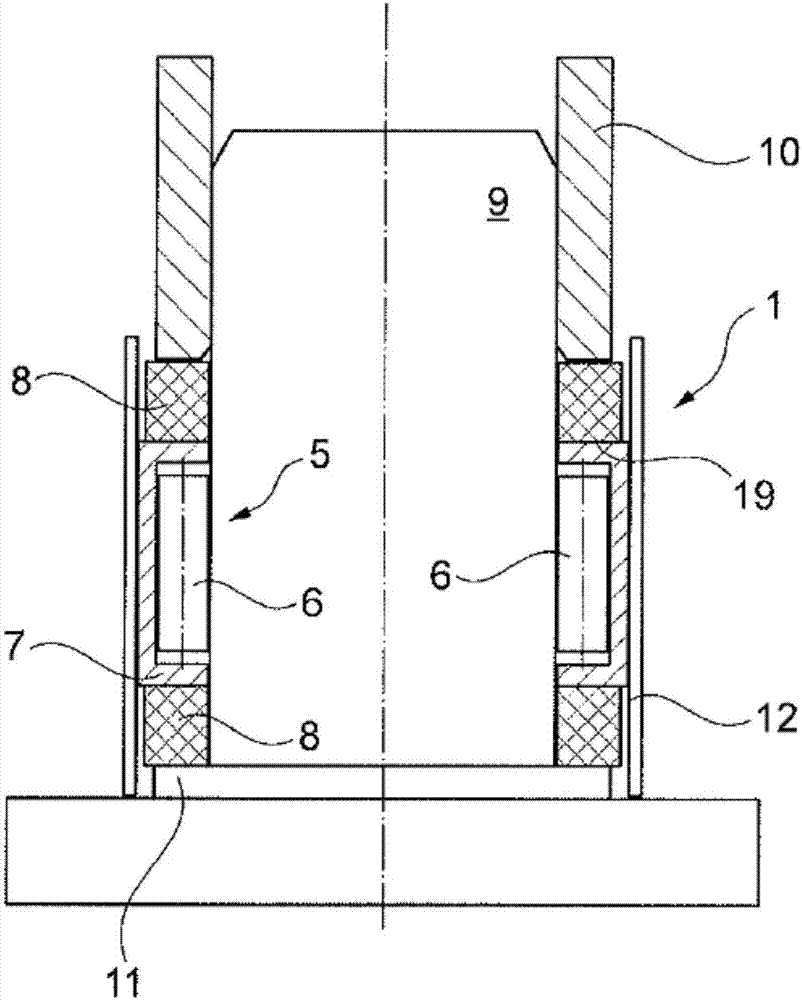
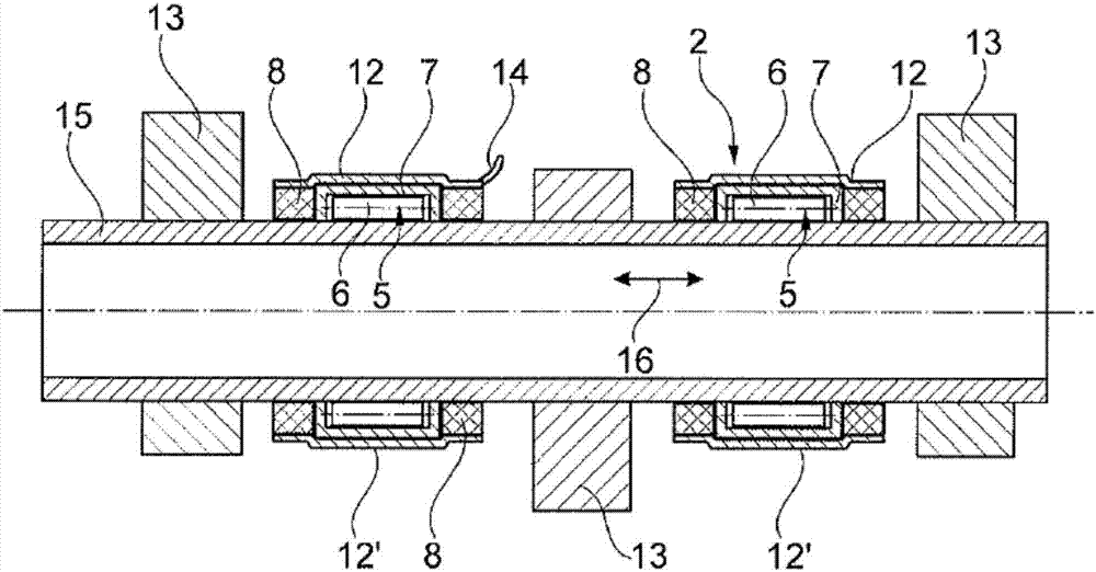
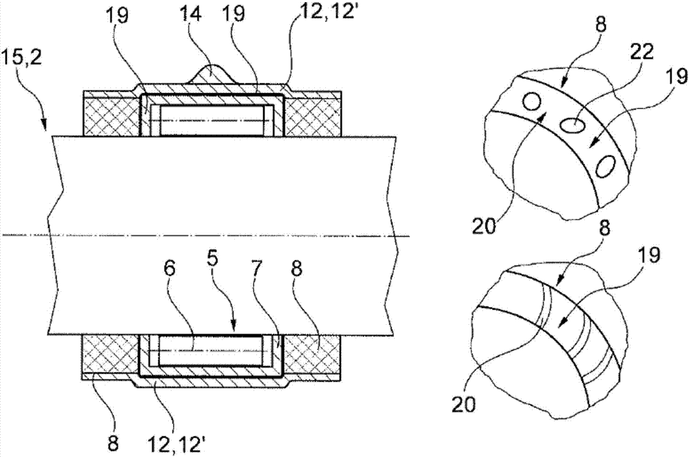
[0020] according to figure 1 , in accordance with the invention for the manufacture of a bearing assembly 1 with which, for example, a control shaft / camshaft 2 is subsequently mounted in a cylinder head 3 or a cylinder head cover 4 (cf. Figure 4 ))), the bearing 5 is first prepared or manufactured by installing or arranging the roller body 6 in the bearing ring 7. The term "control shaft" is frequently synonymous with the term "camshaft" below. The roller bodies 6 can in this case be configured as rollers or needle rollers as well as balls. The bearing 5 with two rings 8 arranged on its front side, in particular with plastic or metal rings, is then pushed onto the assembly mandrel 9 (see figure 1 ), where the two rings 9 are pretensioned towards the front side of the bearing 5 by the corresponding sleeve 10 . This is brought about by the sleeve 10 being pressed onto the upper ring 8 and the lower ring 8 resting on the support or stop 11 of the component mandrel 9 . The te...


PUM


Abstract

The present invention relates to a method of manufacturing a control shaft (2), in particular a camshaft, wherein a bearing (5) is provided, the bearing (5) and the two rings (8) arranged on the front side thereof, (5) to the front side of the bearing (5), pushing the telescopic hose (12) to the bearing (5) and (5) and said two rings (8), the preformed bearing assembly (1) is wound on said two rings (8) and is wound by heating, or the film strip (12 ') is wound around said bearing (5) Withdraw from the component mandrel (9). The production of the control shaft (2) in this way, in particular, can be significantly simplified and less expensive.

Description

technical field [0001] The invention relates to a method of manufacturing a bearing assembly for mounting a control shaft. The invention further relates to a bearing assembly manufactured by this method and a method of manufacturing a control shaft using such a bearing assembly. Background technique [0002] The manufacture of camshafts or control shafts generally takes place mainly by combining individual components, such as bearings and cams, on the camshaft, whereupon the camshaft is ground, especially in the region of the cams, and thus polished. In particular, during this polishing process by grinding, grinding dust is generated which can penetrate into the bearing, in particular into the bearing surface, and stay there, and during the subsequent operation of the internal combustion engine equipped with the camshaft This can lead to increased wear and, in the worst case, even damage to the bearing. For this reason, it is known to protect bearings, such as roller beari...

Claims


Application Information

Patent Timeline
Patent Type & Authority Applications(China)
IPC IPC(8): B24B37/34B24B55/06
CPCB24B37/34B24B55/06F16C35/063F16C41/04F16C19/466F16C2360/18F16H2057/0056F16H2057/005B23P2700/02B23P15/003F01L1/047F01L2001/0476F16C19/522
Inventor 安东尼奥·梅农纳罗兰·沙赫雷尔克里斯托弗·施泰因梅茨克里斯托弗·翁拉特
Owner MAHLE INT GMBH
Learn More