Energy saving and emission reduction gas stove

An energy saving and emission reduction, gas stove technology, applied in the direction of reducing greenhouse gases, household stoves, heating fuels, etc., can solve the problems of gas not easy to fully burn, shorten cooking time, waste, etc., achieve good high temperature isolation, improve heat utilization rate, the effect of slowing the loss of heat

Active Publication Date: 2017-09-15
临沂临港经济开发区市政工程有限公司
View PDF9 Cites 3 Cited by
  • Summary
  • Abstract
  • Description
  • Claims
  • Application Information

AI Technical Summary

Problems solved by technology

The invention has the characteristics of energy saving, emission reduction, health and safety, which improves the heat utilization rate and shortens the cooking time. Due to the isolation effect of the closed frying pan ring, the kitchen realizes zero emission of kitchen fume, which is safe for human health; But this technical solution still exists: 1) The closed frying pan ring makes the kitchen realize the zero emission of cooking fumes in the kitchen, but the high-temperature poisonous waste gas discharged from the gas pipeline is directly discharged to the outside, and these waste gases take away a large amount of heat without being used. 2) Although the closed space has improved a certain heat utilization rate and thermal insulation capacity, the package insulation structure added by the closed space is too large, takes up more space, and is not suitable for large pots. The use of low-end, and no combustion-supporting measures, the closed space makes it difficult for the gas to burn fully

Method used


Image

  • Energy saving and emission reduction gas stove
  • Energy saving and emission reduction gas stove
  • Energy saving and emission reduction gas stove

Examples


Embodiment Construction

[0026] In order to make the object, technical solution and advantages of the present invention clearer, the present invention will be further described in detail below in conjunction with the accompanying drawings.

[0027] It should be noted that, unless otherwise specified, the technical terms or scientific terms used in this application shall have the usual meanings understood by those skilled in the art to which the present invention belongs.

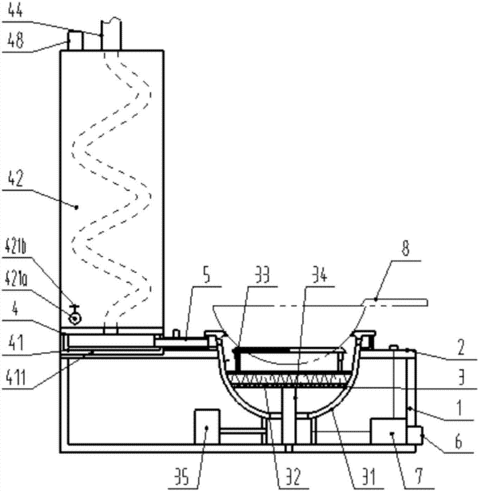
[0028] In the description of the present application, it should be understood that the orientations or positional relationships indicated by the terms "upper", "lower", "left", "right" etc. are based on the attached figure 1 The orientation or positional relationship shown, the orientation or positional relationship indicated by the term "front" is based on the attached figure 1 The "left" shown, the term "rear" indicates the orientation or positional relationship is based on the attached figure 1 The "right" shown is only for the ...


PUM


Abstract

The invention discloses an energy saving and emission reduction gas stove. The energy saving and emission reduction gas stove is matched with a pot body to form closed burning structure design, a burning device comprises a furnace body, a burning disc, a heat collection bearing ring, an ignition device and a combustion fan communicated with the bottom of the furnace body, and the combustion fan can effectively promote gas sufficient burning and improve the combustion efficiency; the heat collection bearing ring is in contact with a pot bottom so that the supporting effect on the pot bottom can be achieved; the transverse radiation direction of a flame can be changed so that longitudinal backflow and reutilization can be sequentially carried out, the good energy saving and emission reduction effects are achieved, and the heat using rate is greatly improved while gas is burnt again; meanwhile, after flameout, disappearing of heat on the burning disc and the heat collection bearing ring can be greatly retarded, and the good heat preservation effect is achieved; meanwhile, a waste heat conversion device greatly absorbs and uses high temperature waste gas heat, and the energy saving and emission reduction aims are effectively achieved; and the beneficial effects of guaranteeing indoor health and sanitation and being high in applicability are achieved, and the energy saving and emission reduction gas stove is suitable for application and popularization.

Description

technical field [0001] The invention relates to the technical field of gas combustion stoves, in particular to an energy-saving and emission-reducing gas stove. Background technique [0002] Existing combustion methods for gas stoves used in homes and catering places are generally open-ended combustion, that is, the combustion disc is exposed, and the flame is in direct contact with the surrounding air during combustion, without any enclosure structure and heat recovery device. The most prominent shortcoming of this combustion method is that the heat loss is large, and trace it to its cause: the one, because be open combustion, the radiation of flame has only a part to be absorbed by the cooking pot bottom, and all the other are radiated in the environment; The heat is transferred to the cooking pot in the form of convective heat exchange with the flue gas, but the temperature of the flue gas leaving the pot is still high, and this part of the heat is wasted. [0003] The C...

Claims


Application Information

Patent Timeline
Patent Type & Authority Applications(China)
IPC IPC(8): F24C3/10F24C3/12F24C15/00F28D7/08F23J15/06F24H1/00
CPCF23J15/06F24C3/10F24C3/126F24C15/001F24H1/00F28D7/082Y02B40/00Y02E20/30
Inventor 郭强
Owner 临沂临港经济开发区市政工程有限公司
Why Eureka
Try Eureka