Eureka AIR delivers breakthrough ideas for toughest innovation challenges, trusted by R&D personnel around the world.

Stable and energy-saving photo-thermal field and control method

An energy-saving, photothermal technology, applied in the field of photothermal electricity, can solve problems such as cycle catastrophic accidents, secondary leakage, and inability to guarantee the salt discharge process, so as to reduce the possibility of intermediate solidification, eliminate the dependence on sealing performance, and improve thermal stability. The effect of utilization efficiency

Pending Publication Date: 2017-09-15
天津滨海设备配套技术有限公司
View PDF8 Cites 0 Cited by
  • Summary
  • Abstract
  • Description
  • Claims
  • Application Information

AI Technical Summary

Problems solved by technology

However, in complex and harsh working environments such as high temperature, acid-base corrosion, etc., the heat resistance and expansion rate of each component material are different, resulting in poor sealing, acid-base working medium entering the bearing, causing sticking, corrosion and secondary leakage
[0004] Moreover, because the trough solar thermal power generation system uses the molten salt medium as the heat collection and heat storage medium at the same time, because the freezing point of the molten salt is very high, the molten salt is very easy to solidify, thus providing a cycle for the entire trough solar thermal power generation system. bring catastrophic accident
How to quickly and stably discharge salt has also become a technical problem. Although some technologies have realized the discharge of high-temperature molten salt, the addition of salt discharge pipelines to the multi-section collector tubes leads to complex structure and high cost of the system, and cannot guarantee the salt discharge process. No residue or solidification occurs

Method used


Image

  • Stable and energy-saving photo-thermal field and control method
  • Stable and energy-saving photo-thermal field and control method
  • Stable and energy-saving photo-thermal field and control method

Examples


Embodiment Construction

[0032] The present invention will be described in further detail below in conjunction with the accompanying drawings and specific embodiments. It should be understood that the specific embodiments described here are only used to explain the present invention, not to limit the present invention.

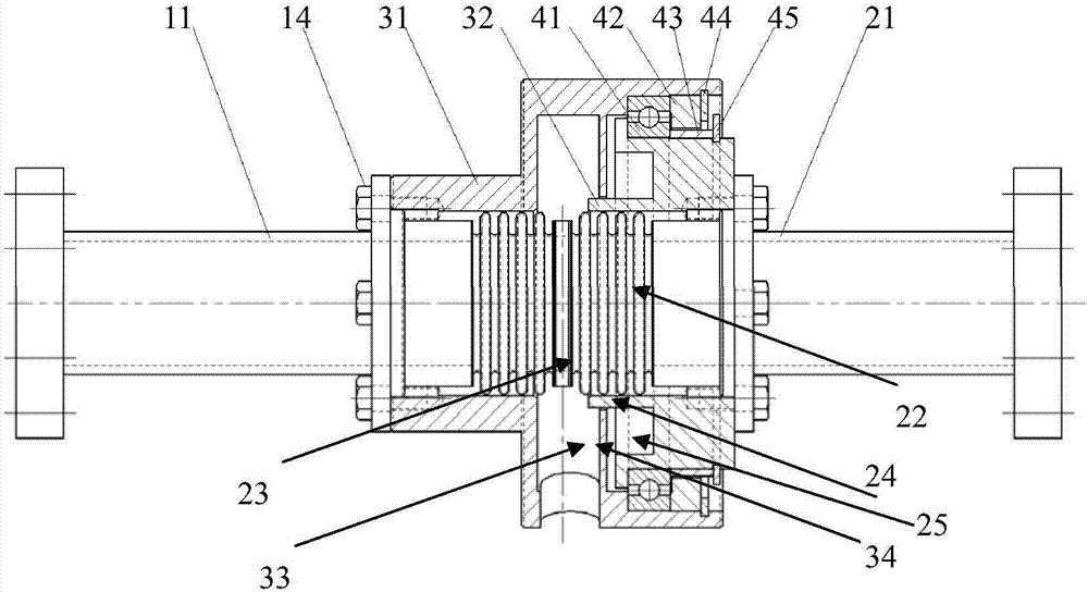
[0033] As shown in the figure, the stable energy-saving photothermal field of the present invention is characterized in that it includes a plurality of sub-trough collectors in series and two salt delivery pipes located on the axially outer sides of the sub-trough collectors on both sides , a high-temperature rotary joint arranged in series on the salt delivery pipe, the high-temperature rotary joint includes,

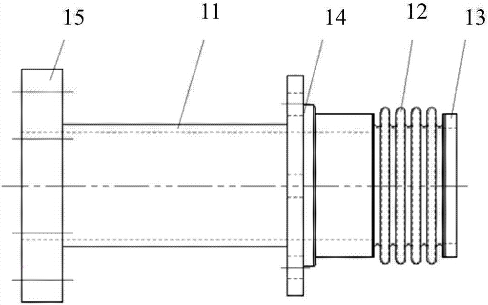
[0034] The first joint includes a first connecting pipe 11, a first metal bellows 12 fixedly connected to the first connecting pipe 11, and a first sealing ring 13 fixedly arranged at the end of the first metal bellows,

[0035] The second joint includes a second connecting p...


PUM


Abstract

The invention discloses a stable and energy-saving photo-thermal field comprising two salt conveying pipes connected to a plurality of sub-tank collectors in series in turn and located at the axial outer sides of the sub-tank collectors at both sides, and high-temperature rotating joints arranged on the salt conveying pipes in series; fixed joints of the rotating joints and the connection of the rotating joints are welded with metal bellows with a certain length and rigidity, and the other end of each metal bellows is welded with wear-resistant sealing rings; upon completion of assembly of the rotating joints, the sealing rings are in butt joint, and the metal bellows are compressed to a certain extent, so that the flexible quantity after hot expansion is utilized effectively, and provided for axial pre-tensioning force required by sealing contact; and at the same time, working spaces of rotating assemblies, such as working medium and bearings, are separated.

Description

technical field [0001] The invention relates to the technical field of photothermoelectricity, in particular to a stable and energy-saving photothermal field and a control method. Background technique [0002] Solar parabolic trough power generation is a technology that uses a linear parabolic reflector that tracks the movement of the sun to gather solar radiation into a heat-absorbing tube located at the focal line of the parabola to heat the heat transfer fluid for power generation. The key equipment of the collector field of the trough power station mainly includes collectors, heat absorbing pipes and heat storage devices. The drive tracking system is the core of the solar collector, and it is the guarantee for the photothermal collector to make full use of solar energy. With a drive tracking system, the solar thermal harvester can track the sun from sunrise to sunset. The swivel joint is an indispensable part for the connection between the heat collecting tube and the ...

Claims


Application Information

Patent Timeline
Patent Type & Authority Applications(China)
IPC IPC(8): F24J2/46F24J2/10F24J2/24F24J2/40F24J2/34F24J2/00F24S10/70F24S23/70
CPCY02E10/44
Inventor 官景栋刘利民
Owner 天津滨海设备配套技术有限公司
Why Eureka
Eureka Blog
Learn More