
A spent fuel transport container waste heat removal device

A transport container and waste heat discharge technology, applied in portable protective containers, nuclear engineering, etc., can solve problems such as inoperability, incomplete process monitoring data, and multi-radioactive solid waste

Active Publication Date: 2019-02-22
NUCLEAR POWER INSTITUTE OF CHINA
View PDF7 Cites 0 Cited by
  • Summary
  • Abstract
  • Description
  • Claims
  • Application Information

AI Technical Summary

Problems solved by technology

[0003] At present, my country's spent fuel intermediate storage capacity and disposal capacity are insufficient. CNNC No. 404 Plant is the only unit in China that can receive spent fuel components from commercial nuclear power plants. The original two pools with a total capacity of 500 tons are full, and the newly built 800-ton pool is not enough for earthquake resistance. The requirements cannot be operated; my country's reprocessing technology is still in the scientific research stage, and the large-scale commercial nuclear fuel reprocessing plant that introduces foreign technology is expected to be put into operation in 2030
[0004] In 2013, the fuel pools of units 1 and 2 of the Daya Bay Nuclear Power Plant were close to full capacity, but the reprocessing plant was unable to receive spent fuel assemblies due to capacity limitations, and the nuclear power plant was facing shutdown, which would bring huge economic losses and social impact
[0005] The existing discharge cooling device requires a special cooling water circulation and filtration circuit. The equipment is relatively complicated, and more radioactive waste will be generated during use. At the same time, there is a lack of filter status monitoring and process monitoring data is incomplete.

Method used


Image

  • A spent fuel transport container waste heat removal device
  • A spent fuel transport container waste heat removal device
  • A spent fuel transport container waste heat removal device

Examples


Embodiment 1

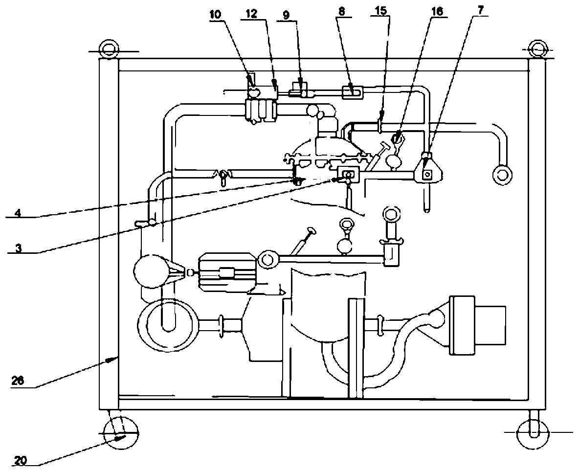
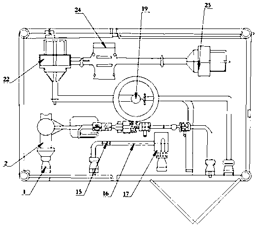
[0053] Such as Figure 1 to Figure 6 As shown, a spent fuel transport container waste heat removal device is characterized in that it includes a water filling circuit, an air charging circuit, an air-water discharge circuit, an air-water separator 19, and an exhaust circuit. The water filling circuit and the air charging circuit share a three-way The valve 7 is connected to the gas-water discharge circuit, the gas-water discharge circuit is connected to the cooling system, and the cooling system is connected to the gas-water separator and then connected to the exhaust circuit;

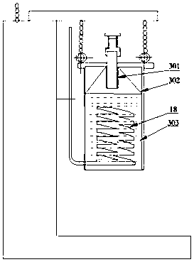
[0054] The cooling system includes an immersion heat exchanger 18, and the immersion heat exchanger 18 is located in the water holding device. The lower end of the heat exchange tube in the immersion heat exchanger 18 is connected with the air-water discharge circuit through a pipeline, and the upper end of the heat exchange tube is connected to the air-water discharge circuit. The water holding device...


PUM


Abstract

The invention discloses a waste heat discharge device for a spent fuel transport container, comprising a water filling circuit, an air charging circuit, an air-water discharge circuit, an air-water separator, and an exhaust circuit. The water filling circuit and the air charging circuit share a three-way valve and are sequentially connected The air-water discharge circuit, the cooling system, the air-water separator, and the exhaust circuit are connected through pipelines. The present invention can independently complete the functions of water filling and boron dissolving, water filling and exhausting, circulating cooling, exhaust gas cooling, steam-water separation, air filtration, container drainage, etc., and a single device can meet the technical requirements of waste heat discharge of spent fuel transport containers. In the present invention, a water-filled boron dissolving process is added: the process is used to dissolve the crystalline boron in the circuit, preventing the circuit from being blocked, and the process is more complete. The invention adopts the submerged heat exchange method, directly immerses the heat exchange components into the submerged heat exchanger, and has good heat exchange effect and simple structure.

Description

technical field [0001] The invention relates to a spent fuel transport container waste heat discharge device for cooling the container, displacing gas and forming a shield in order to ensure that the spent fuel assembly is safely unloaded from the container during the spent fuel transfer process of a pressurized water reactor nuclear power plant. Background technique [0002] my country adopts the "closed nuclear fuel cycle" strategy. The spent fuel of nuclear power plants is temporarily stored in the fuel building for 5 to 10 years. With the decay of high-level radioactive substances in the components and the reduction of their decay heat, they are transported to the reprocessing plant for intermediate storage and processing, and then recycled. The uranium and plutonium in the spent fuel assembly also empties the limited storage space in the pool to meet the operating requirements of nuclear power plants. [0003] At present, my country's spent fuel intermediate storage capa...

Claims


Application Information

Patent Timeline
Patent Type & Authority Patents(China)
IPC IPC(8): G21F5/06G21F5/10
CPCG21F5/06G21F5/10
Inventor 瓮松峰董岱林任荷罗英杨其辉黄辉王炳炎安彦波李鑫
Owner NUCLEAR POWER INSTITUTE OF CHINA
Learn More