Unlock instant, AI-driven research and patent intelligence for your innovation.

Garbage disposal device capable of automatically cleaning cutter and working method of garbage disposal device

A garbage disposal device and automatic cleaning technology, applied in cleaning methods and utensils, cleaning methods using liquids, heating devices, etc., can solve problems affecting the working environment, knives are easy to stick to debris, and easy to produce odors, etc., to improve work environment, facilitate follow-up operations, and increase the effect of cutting force

Active Publication Date: 2017-09-22
桐城市建设投资发展有限责任公司
View PDF5 Cites 3 Cited by
  • Summary
  • Abstract
  • Description
  • Claims
  • Application Information

AI Technical Summary

Problems solved by technology

[0003] Common garbage disposal devices generally transport garbage into the garbage disposal device for crushing and processing. Generally, it takes multiple treatments to process the garbage to the expected level, which affects work efficiency. In the garbage disposal process, the garbage disposal The knives are easy to stick to debris, which can easily affect the normal use of the knives
Due to the special nature of garbage disposal, it is easy to produce peculiar smell during the work process, which affects the working environment

Method used


Image

  • Garbage disposal device capable of automatically cleaning cutter and working method of garbage disposal device
  • Garbage disposal device capable of automatically cleaning cutter and working method of garbage disposal device
  • Garbage disposal device capable of automatically cleaning cutter and working method of garbage disposal device

Examples


Embodiment 1

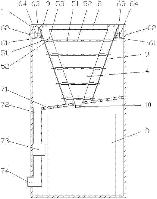
[0030] reference Figure 1-2 , figure 1 A cross-sectional view of a garbage disposal device for automatically cleaning tools provided by the present invention; figure 2 A partial schematic diagram of the garbage crushing device 5 of a garbage disposal device for automatically cleaning cutters provided by the present invention.

[0031] Specifically, a garbage disposal device that automatically cleans knives includes: a housing 1, a feed port 22, a collection box, and a working bucket 4, and also includes a garbage crushing device 5, a knife cleaning device 6, and a waste water collection device 7; The feed port 22 is provided on the housing 1, and the feed port 22 further includes a feed cover 8; the working hopper 4 is provided in the housing 1, and the feed port 22 is located above the working hopper 4. The collection box is located below the working bucket 4; the garbage crushing device 5 includes a crushing knife 51, a number of transmission chains 52, a transmission wheel 5...

Embodiment 2

[0038] reference image 3 , image 3 A cross-sectional view of another garbage disposal device for automatically cleaning cutters provided by the present invention.

[0039] As a preferred mode of the present invention, the crushing knife 51 includes a knife shape with multiple functions, which includes cutting, crushing, grinding, etc. from top to bottom.

[0040] As a preferred mode of the present invention, any functional knife type is provided on at least two transmission chains 52.

[0041] As a preferred mode of the present invention, it further includes a stirring rod 11, a heating tube 12, and a second driving motor 13. The stirring rod 11 is arranged in the collection box 3, and the heating tube 12 is arranged on the stirring rod 11, The stirring rod 11 is connected to the second driving motor 13.

[0042] As a preferred mode of the present invention, a deodorizing device 14 is further included, and the deodorizing device 14 is arranged inside the feed port 22 and above the c...

Embodiment 3

[0048] Reference map

[0049] As a preferred mode of the present invention, it includes the following steps:

[0050] S001: The operator pours garbage into the feed inlet 22, and operates the garbage disposal device to start working;

[0051] S002, the first driving motor 54 drives the transmission wheel 53 to rotate, the transmission wheel 53 drives the transmission chain 52 to work, the crushing knife 51 cuts the poured garbage, and the crushed garbage falls into the collection box 3;

[0052] S003, the water pump 64 works, and the water in the water inlet pipe 62 enters the water spray pipe 63 through the water pump 64 and then is sprayed out by the spray head 61, and the spray head 61 cleans the residue on the crushing knife 51 by spraying water;

[0053] S004: The collection table 71 collects and cleans the waste water of the crushing knife 51 and collects it through the collecting pipe 72. The waste water is filtered through the filter layer 73, and the liquid water is discharged ...


PUM


Abstract

The invention relates to a garbage disposal device capable of automatically cleaning a cutter. The garbage disposal device comprises a shell, a feeding opening, a collecting box and a working hopper; the garbage disposal device is characterized by further comprising a garbage smashing device, a cutter cleaning device and a waste water collecting device; the feeding opening further comprises a feeding cover; the collecting box is located below the working hopper; the garbage smashing device comprises a smashing cutter, a plurality of transmission chains, transmission wheels and a first driving motor; the garbage smashing device is arranged on the inner wall of the working hopper, the transmission chains are arranged on the inner wall of the working hopper, and the first driving motor is connected with the transmission wheels; the smashing cutter is arranged on the transmission chains; the cutter cleaning device comprises a spraying nozzle, a water inlet pipe, a water spraying pipe and a water pump, the water inlet pipe is connected with the water pump, and the water spraying pipe is connected with the spraying head and the water pump; a water separating plate is further arranged between the working hopper and the shell; and the waste water collecting device comprises a collecting table, a water collecting pipe, a filtering layer and a water discharge opening, and the filtering layer is detachable.

Description

Technical field [0001] The invention relates to a garbage processing device, in particular to a garbage processing device that automatically cleans cutters and a working method thereof. Background technique [0002] With the development of urban population, urban garbage has become the primary problem that restricts urban development and environmental pollution. With the rapid development of food processing and catering industries, the output of food waste is increasing rapidly. For example, a large amount of untreated food waste passes through various industries. These channels flow into society, which will seriously affect the water environment and the city's appearance and environment, and endanger people's health and safety. [0003] Common garbage disposal devices generally transport garbage into the garbage disposal device for smashing and processing. Generally, it takes multiple treatments to treat the garbage to the expected level, which affects work efficiency. In the garb...

Claims


Application Information

Patent Timeline
IPC IPC(8): B02C18/14B02C18/16B02C18/24B08B3/02F26B11/14F26B25/04F26B23/00F26B3/24
CPCB02C18/0084B02C18/14B02C18/16B02C18/24B02C2201/06B08B3/02F26B3/24F26B11/14F26B23/00F26B25/04F26B2200/04
Inventor 韩斌
Owner 桐城市建设投资发展有限责任公司
Features
  • R&D
  • Intellectual Property
  • Life Sciences
  • Materials
  • Tech Scout
  • Unparalleled Data Quality
  • Higher Quality Content
  • 60% Fewer Hallucinations
Learn More