Power grid simulation device

A technology of power grid simulation and power grid model, which is applied to circuit devices, harmonic reduction devices, electrical components, etc., can solve the problems of high cost of actual power grid tests and poor software simulation accuracy, so as to improve amplification efficiency, simplify design, and improve switching. The effect of frequency

Inactive Publication Date: 2017-10-03
HUNAN UNIV OF TECH
View PDF2 Cites 4 Cited by
  • Summary
  • Abstract
  • Description
  • Claims
  • Application Information

AI Technical Summary

Problems solved by technology

[0004] The device is connected with the actual load and converter or connected with the hardware-in-the-loop simulation device to simulate various grid forms to quantitatively study the interaction between the grid and grid-connected converter or load, and solve the software problems existing in the current research process. The problem of poor simulation accuracy and high cost of actual power grid test

Method used


Image

  • Power grid simulation device
  • Power grid simulation device
  • Power grid simulation device

Examples


Embodiment 1

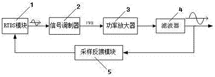
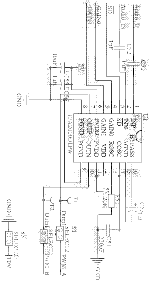
[0032] The invention provides a power grid simulation device, which is mainly composed of five parts: a real-time digital simulation module 1, a signal modulator 2, a power amplifier 3, a filter 4, and a sampling feedback module 5. The real-time digital simulation module 1 is connected to the signal modulator 2, and the signal The modulator 2 is connected to the power amplifier 3, the power amplifier 3 is connected to the filter 4, the filter 4 is connected to the sampling feedback module 5, the sampling feedback module 5 is connected to the real-time digital simulation module 1, and the filter 4 outputs an analog signal; the real-time digital simulation module 1 is used for Establish and simulate the power grid model to generate sinusoidal signals; the power amplifier 3 adopts a digital power amplifier chip using digital power amplifier technology, and adopts a two-stage amplification form. The signal modulator 2 converts the sinusoidal signal with a lower amplitude into a 5V p...

Embodiment 2

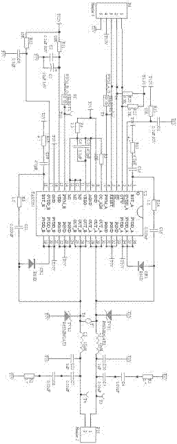
[0052] As in the power grid simulation device described in Embodiment 1, the RTDS is replaced by a controller. The controller generates a three-phase PWM signal by writing a program, controls the inverter bridge to conduct, and generates a PWM wave signal with an amplitude of 0V to the power supply voltage, which is passed through the LC A low-pass filter filters out higher harmonic components. At this time, the controller needs to write SPWM algorithm or SVPWM algorithm program. If a three-phase power supply with flexible adjustment of voltage and frequency is to be obtained, the complexity of controller programming will continue to increase. The device is limited by the switching frequency of the power tube, and the frequency cannot be very high. For example, the maximum frequency of the IGBT is required to be around 50KHz, but its voltage level and power level can be very high. Therefore, this topology is mainly used in occasions that do not require high power quality, and...


PUM


Abstract

The invention relates to a power grid simulation device which is mainly composed of a real-time digital simulation module, a signal modulator, a power amplifier, a filter and a sampling feedback module. According to the invention, the amplification efficiency is greatly improved; the problem that RTDS cannot simulate a large-capacity power grid is solved; the switching frequency is greatly improved; harmonics within 50kHz in an actual power grid can be effectively simulated; the frequency response range is wide; fall and high harmonic power grid forms are realistically simulated; L and C parameter requirements are reduced; the filter design is simplified; the filter size is reduced; a three-phase power amplifier is easily built; the device can conveniently use a step-up transformer to improve the output voltage; the output power is increased through parallel amplifier chips; the constraint of a digital amplifier chip on the output voltage and power is effectively overcome; power grids in a variety of forms are easily simulated; the special condition of the power grid is easily simulated; the frequency response range is wide; and fall and high harmonics and other phenomena are realistically simulated.

Description

technical field [0001] The invention belongs to the field of power state simulation, in particular to a network simulation device. Background technique [0002] When studying the interaction between distributed generation devices, converters and the grid, it is often necessary for the grid to be under some special working conditions, such as voltage sag, three-phase unbalance, frequency fluctuation, background harmonics, etc. For the actual experimental system, due to the particularity of the power grid, it is often difficult to make the above situation occur in the actual power grid, which brings inconvenience to the study of the interaction between the distributed generation device, the converter and the power grid. [0003] When the research object includes the power grid, we will habitually choose power system simulation software, such as matlab, RTDS, PSASP, etc. However, the results obtained by software simulation often cannot accurately reflect the actual situation. ...

Claims


Application Information

Patent Timeline
IPC IPC(8): H02J3/00H02J3/01H02J3/12
CPCH02J3/00H02J3/01H02J3/12H02J2203/20Y02E40/40
Inventor 曾进辉雷敏张晓虎
Owner HUNAN UNIV OF TECH
Why Eureka
Try Eureka