Turbine pressurizer with air inflow compensation device

A technology of turbocharger and compensating device, which is applied to components of pumping devices for elastic fluids, machines/engines, non-variable pumps, etc. Combustion needs and other issues, to achieve the effect of supplementing the intake air volume and improving the intake air flow capacity

Pending Publication Date: 2017-10-10
潍坊富源增压器有限公司
View PDF4 Cites 1 Cited by
  • Summary
  • Abstract
  • Description
  • Claims
  • Application Information

AI Technical Summary

Problems solved by technology

[0003] However, in the prior art, with the continuous increase of engine power and displacement, the requirements for the speed and pressure ratio of the turbocharger are also getting higher and higher, which leads to the fact that the turbocharger with high speed and high pressure ratio In the case of low speed and low pressure ratio, because the air intake is affected by the engine speed, the supercharging effect is not obvious, and it is easy to cause supercharging hysteresis
[0004] Supercharging hysteresis means that in the case of low power output of the engine, the compressor impeller of the turbocharger is affected by the low speed of the turbine and cannot inhale more air, resulting in a reduction in the flow capacity of the airflow at low speeds of the turbine. When the engine is in a state of low power output, the turbocharger cannot meet the combustion requirements of the engine, resulting in insufficient combustion of the engine
Moreover, in the process of converting the engine from low power output to high power output, the supercharging effect of the turbocharger cannot meet the conversion requirements of the engine in time, that is, it cannot inhale and compress enough air in time, and cannot guarantee sufficient response speed , which leads to the problem that the turbocharger is prone to poor responsiveness at low speeds

Method used


Image

  • Turbine pressurizer with air inflow compensation device
  • Turbine pressurizer with air inflow compensation device
  • Turbine pressurizer with air inflow compensation device

Examples


Embodiment Construction

[0021] In order to make the object, technical solution and advantages of the present invention clearer, the present invention will be further described in detail below in conjunction with the accompanying drawings and embodiments. It should be understood that the specific embodiments described here are only used to explain the present invention, not to limit the present invention.

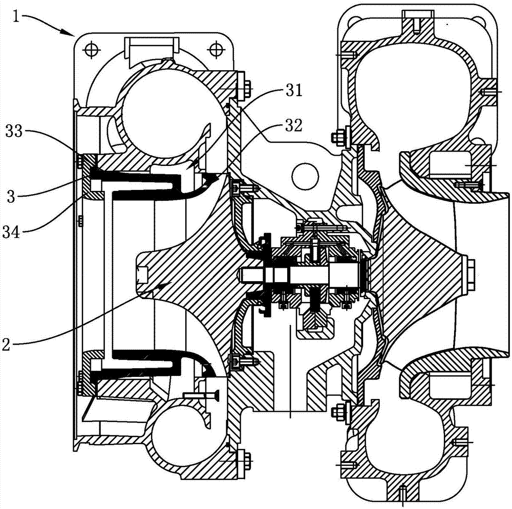
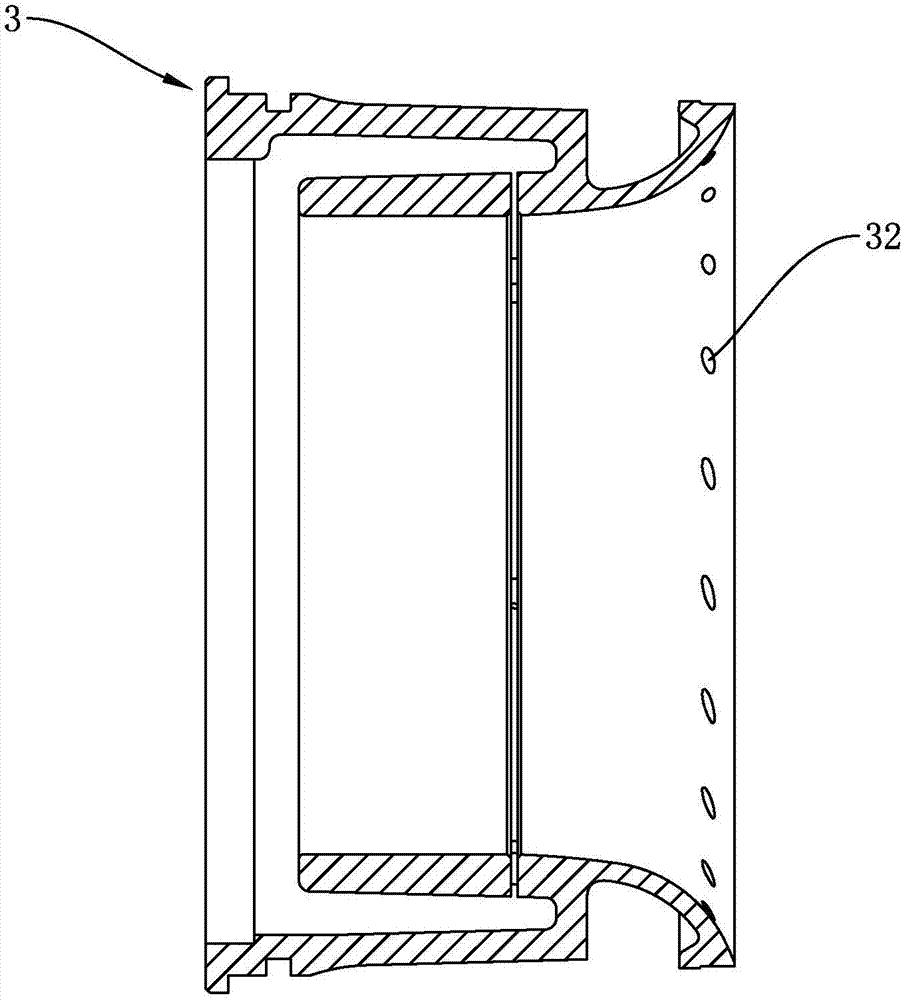
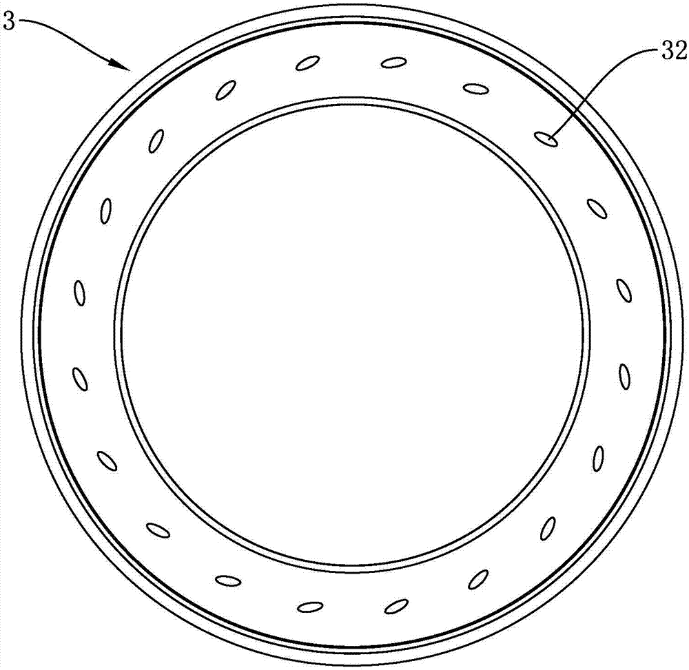
[0022] like Figure 1 to Figure 4 As shown, the present invention includes a compressor casing 1 and a compressor impeller 2. The interior of the compressor casing 1 is provided with a compressor casing insert 3, and a surrounding compressed air is formed between the compressor casing insert 3 and the compressor casing 1. The air intake chamber 31 of the casing insert 3 is provided with a number of air supply holes 32 on the wall of the compressor casing insert 3 in the circumferential direction, and the intake air supply chamber 31 communicates with the compressor impeller 2 through the air supply...


PUM


Abstract

The invention discloses a turbine pressurizer with an air inflow compensation device. The turbine pressurizer comprises an air compressor shell and an air compressor impeller, an air compressor shell insert bush is arranged in the air compressor shell, and the air compressor shell insert bush and the air compressor shell form an air inflow air compensation cavity. The bush wall of the air compressor shell insert bush is provided with air compensation holes in a surrounded mode, the air inflow air compensation cavity communicates with the air compressor impeller through the air compensation holes, and the drilling direction of the air compensation holes are the same as the rotation direction of the air compressor impeller. An air compensation flange is arranged on the outer wall of the air compressor shell and connected with the air inflow air compensation cavity and an outer high-pressure air source. According to the turbine pressurizer with the air inflow compensation device, under the conditions of the low rotating speed and the low pressure ratio, enough air circulation can be supplied to an engine, and the air inflow quantity of the pressurizer is increased; and under the conditions of the low rotating speed and the low pressure ratio, the turbine pressurizer has a high response speed and improves the service effect of the engine.

Description

technical field [0001] The invention relates to the technical field of turbochargers, in particular to a turbocharger with an intake compensation device. Background technique [0002] Turbocharger, that is, the engine intake supercharger, the exhaust gas produced by the combustion of combustible mixture in the engine cylinder enters the turbocharger through the exhaust manifold, and the exhaust gas drives the compressor impeller in the supercharger to the air Compression is performed to increase the density of the air, so that more air enters the cylinder, thereby increasing the engine power, and its supercharging effect is greater than that of a mechanical supercharging. [0003] However, in the prior art, with the continuous increase of engine power and displacement, the requirements for the speed and pressure ratio of the turbocharger are also getting higher and higher, which leads to the fact that the turbocharger with high speed and high pressure ratio In the case of l...

Claims


Application Information

Patent Timeline
Patent Type & Authority Applications(China)
IPC IPC(8): F04D29/40F02B37/10
CPCF02B37/10F04D29/403F05D2220/40Y02T10/12
Inventor 王新江马爱民陈良牟国松王忠起范成张永莲杜智萍宫建民
Owner 潍坊富源增压器有限公司
Why Eureka
Try Eureka