An Advanced Controller Design Method for Active Sidestick
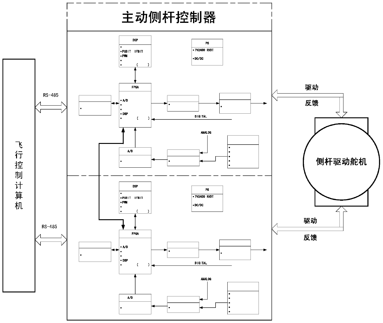
A technology of active side levers and design methods, applied in the direction of program control, program control, and electrical program control in sequence/logic controllers, can solve problems such as blank engineering products, improve technology maturity, and shorten task cycles , Improve the effect of control accuracy
- Summary
- Abstract
- Description
- Claims
- Application Information
AI Technical Summary
Problems solved by technology
Method used
Image
Examples
Embodiment 1
[0071] Armature current acquisition circuit:
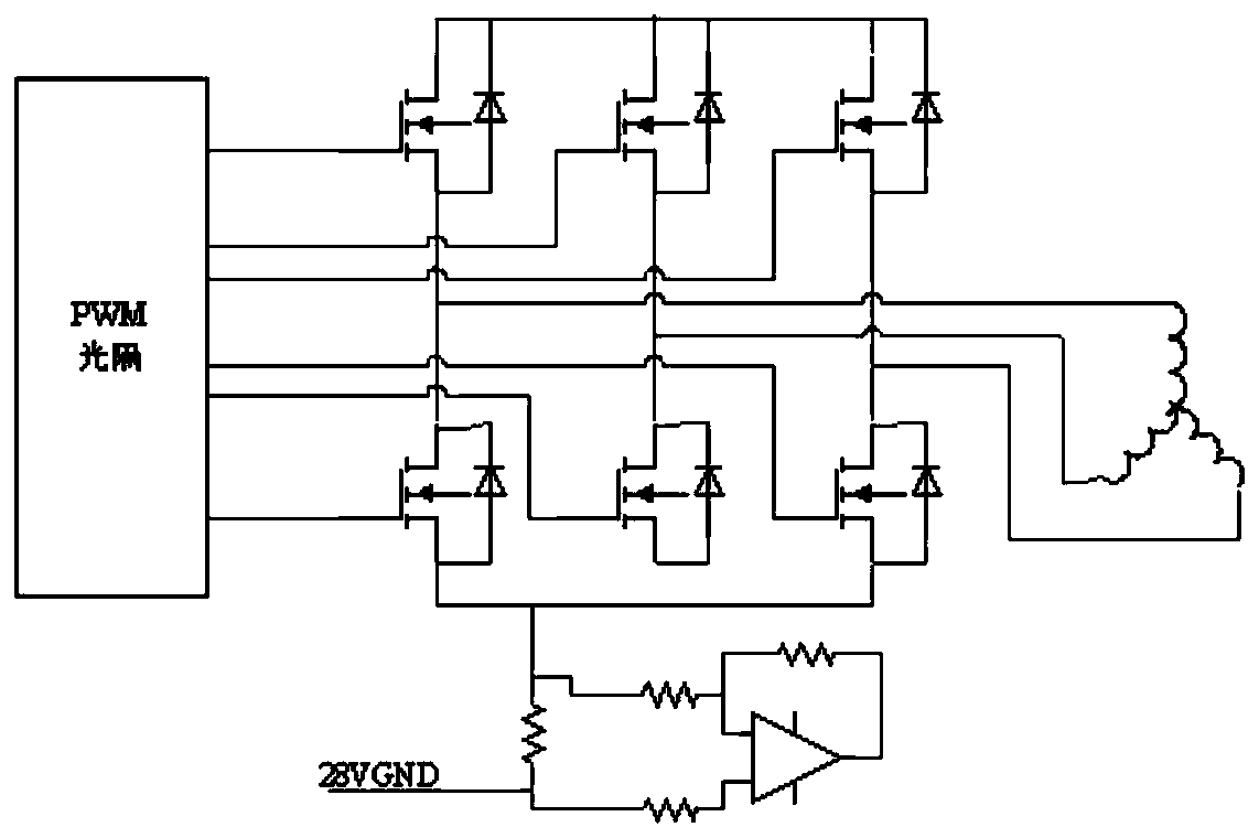
[0072] Sampling resistors are used to collect armature current, and after two-stage amplifying circuit and first-order RC filtering, the voltage signal is output to the analog-to-digital converter after impedance transformation. Considering that the maximum input current is 2A, two 1Ω, 3W, 0.5% precision resistors are connected in parallel for the acquisition resistor, and the differential input current signal is converted into a voltage signal, and then amplified by the operational amplifier OP4177, adding a time constant of 9.912us- The first-order filter is finally output to the analog-to-digital conversion module in the form of voltage to ensure the accuracy of current acquisition.
[0073] a) The model of the 1Ω current acquisition resistor is: GRM3263-3W-1Ω-J-K-GJB1432B, connected in parallel through the resistor, the sampling resistance is 0.5Ω, V in = I in ×0.5;
[0074] b) The first-stage amplifying circuit is mainly u...
Embodiment 2
[0079] Rotor position resolver demodulation circuit:
[0080] The positive and cosine reluctance is used as the motor rotor position sensor, and the dedicated decoding chip AU6802N1 is used for analog-to-digital conversion. The dedicated decoding chip can generate the AC excitation of the resolver sensor, and decode the sine and cosine signals output by the sensor, and finally convert It is the digital quantity of the position signal, which is transmitted to the field programmable gate array through the serial bus for collection, and then enters the processor for loop synthesis.
[0081] The specific implementation method is as follows:
[0082] a) AU6802N1 resolver demodulation chip circuit
[0083] According to the requirements of the chip manual, connect the peripheral circuit of AU6802N1, the crystal oscillator is M55310 / 16-B31A-20M00000, the clock frequency is 20MHz, the key pin connection method of AU6802N1 is as follows:
[0084] pin number meaning Setti...
PUM
 Abstract
Description
Claims
Application Information
 - R&D
- Intellectual Property
- Life Sciences
- Materials
- Tech Scout
- Unparalleled Data Quality
- Higher Quality Content
- 60% Fewer Hallucinations
Browse by: Latest US Patents, China's latest patents, Technical Efficacy Thesaurus, Application Domain, Technology Topic, Popular Technical Reports.
© 2025 PatSnap. All rights reserved.Legal|Privacy policy|Modern Slavery Act Transparency Statement|Sitemap|About US| Contact US: help@patsnap.com


