Chip device for female tumor marker joint inspection in multi-driving mode coupling operation

A tumor marker, multi-drive technology, applied in the field of analysis and testing, can solve the problems of micro-channel bubbling substrate and cover, PDMS micro-channel inner surface modification, troublesome operation, large flow resistance, etc.

Pending Publication Date: 2017-10-24
葛宇杰
View PDF9 Cites 0 Cited by
  • Summary
  • Abstract
  • Description
  • Claims
  • Application Information

AI Technical Summary

Problems solved by technology

[0008] But it's not that simple
[0009] First, this polydimethylsiloxane material, the material referred to by the acronym PDMS, is itself a strongly hydrophobic material. Microchannels are built on this material. If the microchannels are not targeted The modification operation of the surface of the channel, then, after the overall assembly is completed, that is, after the cover is covered, because the inner surface of the micro channel in the structure occupies most of the inner surface of the liquid flow channel, then the PDMS micro channel The strong hydrophobic characteristic of the inner surface of the channel is the decisive factor, which will make it very difficult for the polar liquid flow similar to the aqueous solution to pass through, and its flow resistance is so large that even ordinary micropumps are difficult to push. Of course, If the cover sheet also chooses to use the PDMS material, then the problem is basically the same, with little difference; therefore, in the prior art, it is necessary to modify and modify the inner surface of the microchannel on the PDMS material; then , is this modification operation for the inner surface of the PDMS microchannel very troublesome? That's not the problem. What constitutes a serious technical problem is another problem: the PDMS polymer molecules in the bulk phase of the PDMS material substrate have the characteristics of automatic diffusion and migration to the surface. The characteristics of polymer molecules diffusing and migrating to the surface automatically will make the modified state of the inner surface of the microchannel modified by the surface modification unable to maintain for a long enough time, and the microgroove after surface modification The maintenance time of the inner surface state of the channel is roughly only enough to complete the time required for the internal test experiment in the laboratory; in other words, the inner surface of the PDMS microchannel after surface modification or surface modification is formed after modification The surface state of the surface does not last long, but quickly tends to or changes back to the surface state before the surface modification, and returns to the original strongly hydrophobic surface state in a relatively short period of time. Then, just imagine, Can such microfluidic chips be produced in large quantities, stored in large quantities, and widely promoted? The answer is obvious, that is, impossible
[0017] Third, as mentioned above, the inner surface of the PDMS microchannel is strongly hydrophobic, and targeted surface chemical modification or surface chemical modification is difficult to last. It is effective to use it within a short period of time; if the relatively short expiration date has passed and it is still used forcibly, since the surface state is already close to the hydrophobic state, there must be a comparison between using the conventional micropump to drive the sample liquid flow. Large flow resistance, in this way, the sample liquid can only be forced to flow in the target direction by increasing the pumping power and pumping pressure of the micropump. Pumping pressure to pump the sample liquid flow will cause bubbling, puffing, twisting, and deformation of the microchannels at the sampling end of the substrate including the area near the sampling end, and, under such high pressure conditions, The microgroove and its periphery at the sample inlet and its vicinity are also prone to peeling between the substrate and the cover slip. In this case, the sample solution will enter between the substrate and the cover slip formed after the peeling. This actually leads to the damage of the microfluidic chip; of course, if the surface modification or the surface modification is not in place, it will also lead to the above-mentioned situation within the short customary validity period; In the case of simply using an external micropump for liquid flow drive, the above-mentioned problem always exists
As mentioned above, if no pre-operations such as surface modification or surface modification have been done at all, then the above-mentioned problem will be more serious, even if the microchannel bubbling at the injection end and its vicinity does not occur , puffing, twisting, deformation, and peeling between the substrate and the cover sheet, etc., just because the flow resistance is too large, the use of a high-pressure micropump may not be able to drive the sample liquid flow toward the terminal.

Method used


Image

  • Chip device for female tumor marker joint inspection in multi-driving mode coupling operation

Examples


Embodiment Construction

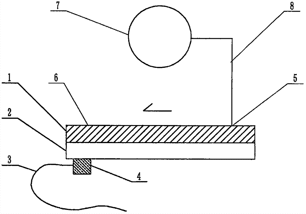
[0071] exist figure 1 In the example shown in this case, the feature of this example is that the structure of the device includes a microfluidic chip, and the structure of the microfluidic chip includes a substrate 1 and a cover sheet 2 that are attached to each other and installed together. Both the substrate 1 and the cover 2 are plates or sheets, and the surface of the substrate 1 facing the cover 2 contains a channel structure formed by a molding process or an etching process, and they are attached to each other and installed on the Together, the substrate 1 and the cover sheet 2 construct a microfluidic chip containing a pipeline structure. The ports are respectively connected to the sampling port 5 and the terminal 6 of the microfluidic chip, the sampling port 5 is the injection port of the sample solution of the microfluidic chip, and the terminal 6 is the injection port of the microfluidic chip for the actual sample injection test. The terminal of the flow of the samp...


PUM

PropertyMeasurementUnit
Thicknessaaaaaaaaaa
Diameteraaaaaaaaaa
Lengthaaaaaaaaaa

Abstract

The invention relates to a chip device for female tumor marker joint inspection in multi-driving mode coupling operation, and belongs to the field of analysis and test. If PDMS (polydimethylsiloxane) is used for manufacturing a substrate of a female applicable micro-fluidic chip for typical tumor marker joint inspection, the advantages in the price and process are realized, but the difficult problems also exist. The scheme aims at the difficult problems and is characterized in that the substrate selects the PDMS with the original ecology surface; a miniature ultrasonic transducer is fixedly arranged in an adjacent position of the specimen liquid flow terminal of the micro-fluidic chip; meanwhile, the sampling end of the micro-fluidic chip is provided with an ultrasonic attenuator; the effect that the ultrasonic intensity is fast decreased progressively in short distance is achieved, so that the interfacial tension difference is formed at two ends of the chip; the difference provides force for driving specimen liquid flow to flow along a hydrophobic capillary channel towards the terminal direction; the power is mutually coupled and collaboratively operated with micropump mechanical pumping power contained in the structure at the same time.

Description

technical field [0001] The invention relates to a chip device for combined detection of female tumor markers with multi-drive mode coupled operation, belonging to the field of analysis and testing. Background technique [0002] Tumor markers (tumor markers, TM) refer to a class of substances produced by tumor cells themselves or produced by the body's response to tumor cells during the occurrence and proliferation of tumors, reflecting the existence and growth of tumors, including Proteins, hormones, enzymes (isoenzymes) and oncogene products, etc. Testing the tumor markers in the patient's blood or body fluids can detect tumors early in the tumor screening, observe the curative effect of tumor treatment and judge the prognosis of patients. Currently, the tumor markers commonly used clinically are: (1) alpha-fetoprotein (AFP) is a marker for primary liver cancer, testicular cancer, ovarian cancer and other tumors; (2) carcinoembryonic antigen (CEA) is a marker for digestive...

Claims


Application Information

Patent Timeline
IPC IPC(8): B01L3/00G01N33/574
Inventor 李榕生葛宇杰
Owner 葛宇杰
Why Eureka
Try Eureka