Supercharge Your Innovation With Domain-Expert AI Agents!

Redundant system of engine rotating speed and phase sensors and control method of redundant system

A phase sensor, engine speed technology, applied in engine control, machine/engine, electrical control and other directions, can solve problems such as insurmountable, signal error, signal error, etc., to achieve convenient overall layout, stable system operation, and reduce design costs Effect

Pending Publication Date: 2017-10-24
芜湖钻石航空发动机有限公司
View PDF9 Cites 8 Cited by
  • Summary
  • Abstract
  • Description
  • Claims
  • Application Information

AI Technical Summary

Problems solved by technology

Especially in the field of aviation, the key inputs in the electronic control system such as speed sensor, phase sensor, intake air temperature / pressure sensor, controller ECU (Electronic Control Unit) is a dual redundant design, and the input of each controller is independent , the output shares one channel, which can ensure the relative independence of the two systems. At the same time, in order to ensure that the input information of the two controllers is as similar as possible, the same output can be obtained. Therefore, the position of the sensor in the redundant design is required to be as possible as possible. Together, this not only increases the difficulty of the overall layout of the engine, but also because the sensors are not completely in the same position, the collected signals will have errors, which will eventually lead to errors in the output, which is manifested in large fluctuations in engine power when switching input channels , or even engine failure, causing the engine to stall
[0004] To sum up, there are the following problems in the prior art: due to the layout of the dual input channels cannot be completely at the same point, especially the signal collected by the speed sensor will have certain errors, resulting in the two controllers can not guarantee completely consistent output , in the process of switching controllers, it will cause large fluctuations in engine power, or engine failure
[0005] In view of the above problems, the patent application with the publication number CN106593761A, the patent title is "A Redundancy and Injection Method Based on ETPU Four-Cylinder Diesel Engine", discloses the crankshaft sensor corresponding to the main generator controller and the corresponding sensor of the auxiliary generator controller. The difference between the crankshaft sensors is 180 degrees. Although the difference between the two is 180 degrees, whether the two detect the same signal tooth, and the positional relationship between the two cam phase sensors is not clear, and the error problem when switching the input channel cannot be overcome. to overcome the occurrence of the above

Method used


Image

  • Redundant system of engine rotating speed and phase sensors and control method of redundant system
  • Redundant system of engine rotating speed and phase sensors and control method of redundant system

Examples


Embodiment Construction

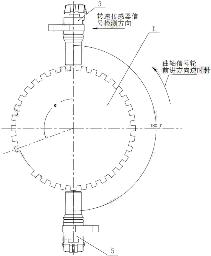
[0022] like figure 1 As shown, the first crankshaft speed sensor 3 and the second crankshaft speed sensor 5 share a crankshaft signal wheel 1, and the center line of the first crankshaft speed sensor 3 is along the rotation direction of the crankshaft signal wheel 1 and the center of the first tooth of the crankshaft signal wheel 1 after missing teeth. Lines form a certain angle, and the center line of the second crankshaft speed sensor 5 forms an angle of 180° with the centerline of the first crankshaft speed sensor 3 along the direction of rotation of the crankshaft signal wheel 1. Now, the piston of the first cylinder of the engine is at compression top dead center.

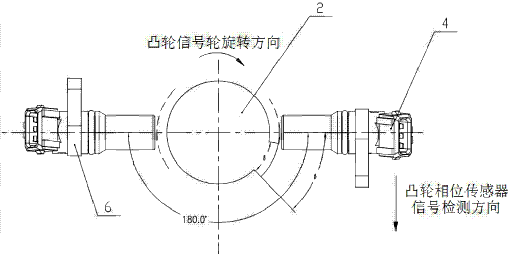
[0023] like figure 2 As shown, the first cam phase sensor 4 and the second cam phase sensor 6 share a cam signal wheel 2, and when the piston of the first cylinder of the engine is at compression top dead center, the center line of the first cam phase sensor 4 is along the rotation direction of the cam signal...


PUM


Abstract

The invention discloses a redundant system of engine rotating speed and phase sensors. A crankshaft signal wheel and a cam signal wheel are arranged on an output shaft of an engine. The system is provided with a first crankshaft rotating speed sensor, a second crankshaft rotating speed sensor, a first cam phase sensor and a second cam phase sensor, wherein the first crankshaft rotating speed sensor and the second crankshaft rotating speed sensor are used for collecting the signal of the crankshaft signal wheel and spaced by 180 degrees, and the first cam phase sensor and the second cam phase sensor are used for collecting the signal of the cam signal wheel and spaced by 180 degrees. The redundant system has the beneficial effects that the crankshaft rotating speed sensors and the cam phase sensors in redundant design are arranged in the 180-degree included angle manner correspondingly, and the engine is overall arranged conveniently; on the basis of the above structure, natural switching of two channels can be achieved through an exactly-identical control program; control is simple; stability and reliability are achieved; and faults possibly generated during controller channel switching can be completely avoided.

Description

technical field [0001] The invention relates to the technical field of engines, in particular to the redundant design of rotational speed and phase sensors of aeroengines. Background technique [0002] The engine is the core component of power machinery. With the application of electronic technology in engine technology, the electronic control system becomes the brain and nervous system of the engine. Its function and reliability directly affect the function and reliability of the engine. As the crankshaft speed sensor and cam phase sensor in the control system, they not only directly affect the starting performance of the engine, but also have an important impact on the normal operation of the engine. [0003] At present, no matter in the field of automobile or aviation, the redundant design of electronic control system, especially the redundant design of key sensors, has already begun to be used. Especially in the field of aviation, the key inputs in the electronic contro...

Claims


Application Information

Patent Timeline
Patent Type & Authority Applications(China)
IPC IPC(8): F02D41/30F02D41/14
CPCF02D41/1401F02D41/3064F02D2200/101F02D2200/10
Inventor 唐艳荣郑君刘刚胡崇波周佳黄夫龙肖蕤卞少春侯尊江佩索国安周昊洪楠熊骏华余凯璐卢东亮
Owner 芜湖钻石航空发动机有限公司
Features
  • R&D
  • Intellectual Property
  • Life Sciences
  • Materials
  • Tech Scout
  • Unparalleled Data Quality
  • Higher Quality Content
  • 60% Fewer Hallucinations
Learn More