Ultrathin heat pipe and manufacturing method thereof

A technology of ultra-thin heat pipes and manufacturing methods, which is applied in the field of heat conduction, and can solve the problems of wire mesh inner core falling off, too high requirements for metal mesh, unfavorable heat dissipation, etc., and achieve the effects of not easy to disperse, convenient operation of process steps, and compact structure

Pending Publication Date: 2017-10-24
杭州瀚亨实业有限公司
View PDF6 Cites 7 Cited by
  • Summary
  • Abstract
  • Description
  • Claims
  • Application Information

AI Technical Summary

Problems solved by technology
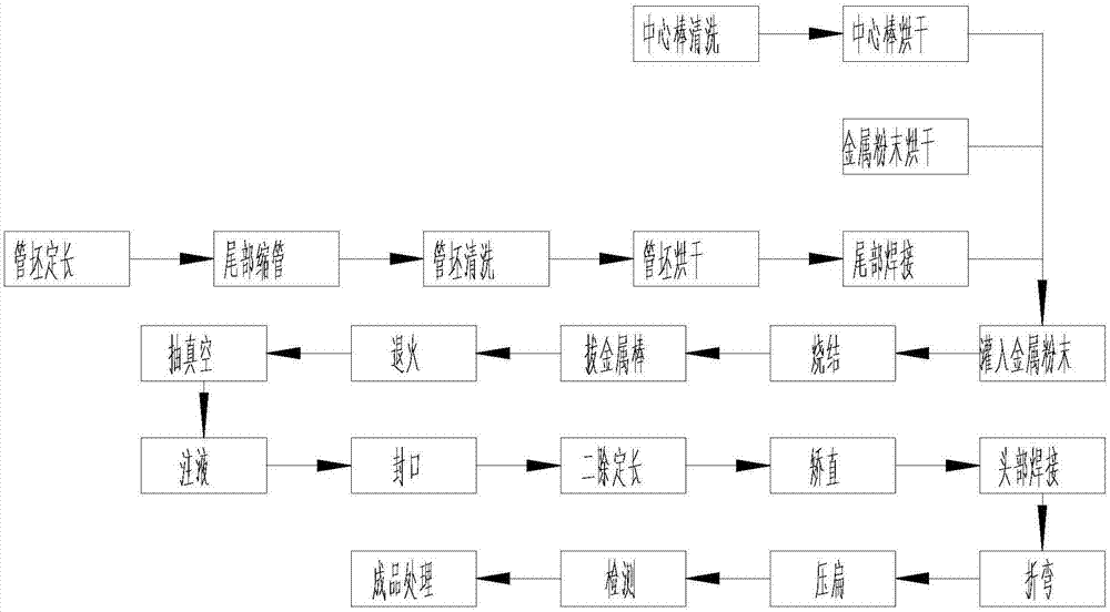
The liquid-absorbing core structure has too high requirements on the wire mesh, which limits the further reduction of the thickness of the ultra-thin heat pipe, and the inner core of the wire mesh is easy to partially fall off when the pipe is bent, which is not conducive to heat dissipation

Method used


Image

  • Ultrathin heat pipe and manufacturing method thereof
  • Ultrathin heat pipe and manufacturing method thereof
  • Ultrathin heat pipe and manufacturing method thereof

Examples


Embodiment 1

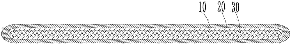
[0094] refer to Figure 1-2 , an ultra-thin heat pipe, comprising a metal pipe body 10, a liquid-absorbing core 20 and a working medium 30;

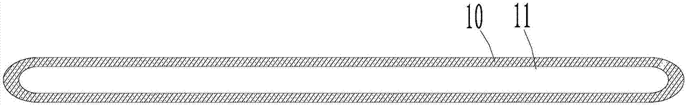
[0095] The wall thickness of the metal pipe body 10 is 0.10 mm, and its tail and head are sealed ends. The metal pipe body is a flat metal pipe body with an airtight inner cavity 11; The necking part of the tail is welded to form the tail sealing end, and the head of the metal pipe body is welded to form the head sealing end.

[0096] The liquid-absorbing core 20 is arranged in the sealed inner cavity 11 of the metal pipe body 10, and the liquid-absorbing core 20 is a metal powder sintered capillary layer with uniform thickness formed by bonding the metal powder to the inner wall of the metal pipe body through high-temperature sintering;

[0097] The working medium 30 is filled in the sealed inner chamber 11 of the metal pipe body 10 . During the working process, the working medium can penetrate into the metal powder sintered capillary l...

Embodiment 2

[0126] The feature of this embodiment is that the metal powder sintered capillary layer is evenly distributed on the entire inner wall of the metal pipe body, and the thickness of the metal powder sintered capillary layer is 0.05 mm. The wall thickness of the metal pipe body is 0.03 mm. The overall thickness of the ultra-thin heat pipe is 0.20 mm. The metal powder is aluminum powder with a particle size of 200-300 mesh. The working medium is a mixed solvent of acetone and pure water in any ratio.

[0127] Others are the same as in Example 1.

Embodiment 3

[0129] The characteristics of this embodiment are: the metal powder sintered capillary layer is uniformly distributed on the entire inner wall of the metal pipe body, and the thickness of the metal powder sintered capillary layer is 0.10 mm. The wall thickness of the metal pipe body is 0.05 mm. The overall thickness of the ultra-thin heat pipe is 0.50mm. The metal powder is magnesium powder, and the particle size is 200-300 mesh. The working medium is a mixed solvent of ethanol and pure water in any ratio.

[0130] Others are the same as in Example 1.


PUM

PropertyMeasurementUnit
thicknessaaaaaaaaaa
thicknessaaaaaaaaaa
thicknessaaaaaaaaaa

Abstract

The invention discloses an ultrathin heat pipe. The ultrathin heat pipe comprises a metal pipe body, a liquid sucking core and a working medium; the wall thickness of the metal pipe body is 0.03-0.10 mm; the tail part and the head part of the metal pipe body are both sealing ends; the metal pipe body is a flat metal pipe body with a closed inner cavity; the liquid sucking core is arranged in the closed inner cavity of the metal pipe body; the liquid sucking core is a metal powder sintering capillary layer formed by bonding metal powder on the inner wall of the metal pipe body after high-temperature sintering; and the closed inner cavity of the metal pipe body is filled with the working medium. The invention further discloses a manufacturing method of the ultrathin heat pipe. The ultrathin heat pipe has the characteristics of smooth gas-liquid channel separation, good heat transfer performance, high capillary force and low backflow resistance of the working medium. The manufacturing method has the characteristics of convenience in operation of process steps, high production efficiency and adaption to large-batch production, and can effectively prevent drapes and recesses formed in the manufacturing process of the ultrathin heat pipe.

Description

technical field [0001] The invention relates to a heat pipe, in particular to an ultra-thin heat pipe and a manufacturing method thereof, belonging to the technical field of heat conduction. Background technique [0002] With the rapid development of micro-nano electronic technology, the power density of chips continues to rise, and the problem of thermal barriers has become a bottleneck restricting the further development of small electronic devices such as high-performance smartphones and tablet computers. At present, heating elements such as smart chips and cameras are generally cooled by forced air convection, but this method needs to be equipped with a high dedicated fan. Due to the low heat capacity and thermal conductivity of the air, its cooling capacity is very limited. It is difficult to adapt to the heat dissipation requirements of the growing high-power chips. The serious heating problem caused by untimely heat dissipation has greatly damaged the user's operatin...

Claims


Application Information

Patent Timeline
Patent Type & Authority Applications(China)
IPC IPC(8): F28D15/04
CPCF28D15/046
Inventor 张洪锋吴海涛傅洁泉
Owner 杭州瀚亨实业有限公司
Why Eureka
Try Eureka