

Active rectifier
A technology of rectifier and comparator, which is applied in the direction of conversion of AC power input to DC power output, high-efficiency power electronic conversion, and output power conversion device. The effect of the phenomenon
- Summary
- Abstract
- Description
- Claims
- Application Information
AI Technical Summary
Problems solved by technology
Method used
Image

Examples
Embodiment approach 1
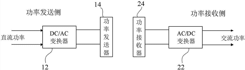
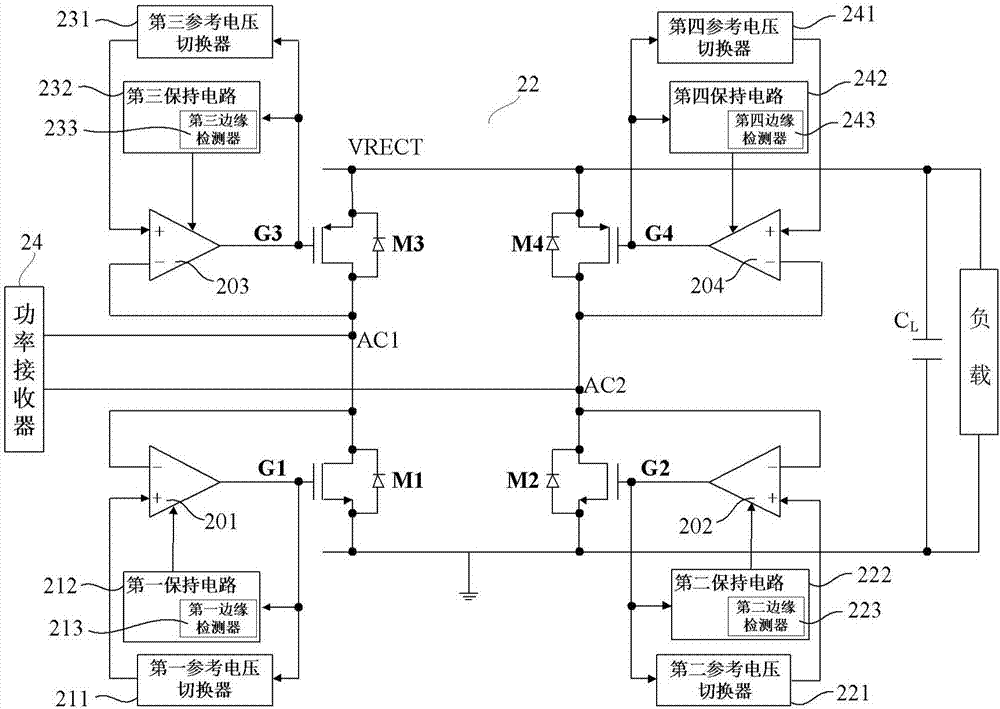
[0038] figure 1 is a conceptual diagram showing a wireless charging system, figure 2 is a schematic diagram showing an active rectifier according to Embodiment 1 of the present invention, and shows figure 1 A schematic diagram of the specific structure of the AC / DC converter (ie rectifier) 22 in FIG.
[0039] like figure 2 As shown, the active rectifier 22 (hereinafter, sometimes simply referred to as a rectifier) includes: first to fourth switching elements MI to M4, first to fourth comparators 201 to 204, first to fourth reference voltage switches 211 ˜241, the connection point AC1 between the first switching element M1 and the third switching element M3, and the connection point AC2 between the second switching element M2 and the fourth switching element M4. The diodes connected in parallel to the first to fourth switching elements M1 to M4 represent the parasitic capacitance of each switching element itself. A power receiver 24 is connected between the connection...
Deformed example 1
[0050] Image 6 is a schematic diagram showing an active rectifier according to Modification 1 of the present invention. and figure 2 Compared with the structure of , the difference is that Image 6 In the shown rectifier 22', the third and fourth switching elements M3', M4' are also N-channel type MOS transistors. When an N-channel MOS transistor is used on the high-level side of the load, it can be applied to a high-voltage, high-power wireless charging system, and can improve the conversion efficiency of the rectifier. Since an N-channel MOS transistor is used on the high level side, the output of the third comparator 203 and the fourth comparator 204 are boosted by the first boost converter 234 and the second boost converter 244 and then applied to Gates of the third and fourth switching elements M3', M4'. Other structures and effects and figure 2 The rectifiers are the same, so repeated descriptions are omitted.
Embodiment approach 2
[0052] Figure 7It is a schematic diagram showing the active rectifier according to Embodiment 2 of the present invention. and figure 2 Compared with the structure of , the difference is that in Figure 7 In the shown rectifier 42, there are reference voltage switches (411 and 421) only on the sides of the first switching element M1 and the second switching element M2. On the gate side of the third switching element M3, the output G2 of the second comparator 202 is input through the first inverter 431; on the gate side of the fourth switching element M4, the first comparator is input through the second inverter 441. The output G1 of the device 201. In addition, the rectifier 42 may further have first and second holding circuits 412 , 422 , and first and second edge detection circuits 413 , 423 . Other structures and effects and figure 2 The rectifiers are the same, so repeated descriptions are omitted.
[0053] and figure 2 Compared with the active rectifier 22 of th...
PUM
 Abstract
Description
Claims
Application Information