Bead core covering method and bead core covering device

A coating device and bead core technology, which is applied in the field of bead core coating and bead core coating devices, can solve the problems of sheet parts damage, wrinkles, and shortened length of side sheet parts, so as to prevent dimensional changes, Improve the effect of poor adhesion

Active Publication Date: 2017-10-31
TOYO TIRE & RUBBER CO LTD
View PDF7 Cites 4 Cited by
  • Summary
  • Abstract
  • Description
  • Claims
  • Application Information

AI Technical Summary

Problems solved by technology

Therefore, there is a possibility that the length of the sheet member on the outer peripheral surface becomes short or the sheet member is damaged due to tension.
In addition, since tension is applied from the inner peripheral surface side to the outer peripheral surface side and rolled up, the sheet member is warped during the rolling up, causing wrinkles.
[0007] On the other hand, when the covering rubber is rolled up from the outer peripheral surface side to the inner peripheral surface side along the cross-sectional shape of the bead core as in Patent Document 2, the peripheral length of the inner peripheral surface of the bead core is longer than that of the outer peripheral surface. Since the circumference is short, the covering rubber remains on the inner peripheral surface, and wrinkles may occur

Method used


Image

  • Bead core covering method and bead core covering device
  • Bead core covering method and bead core covering device
  • Bead core covering method and bead core covering device

Examples


no. 1 approach

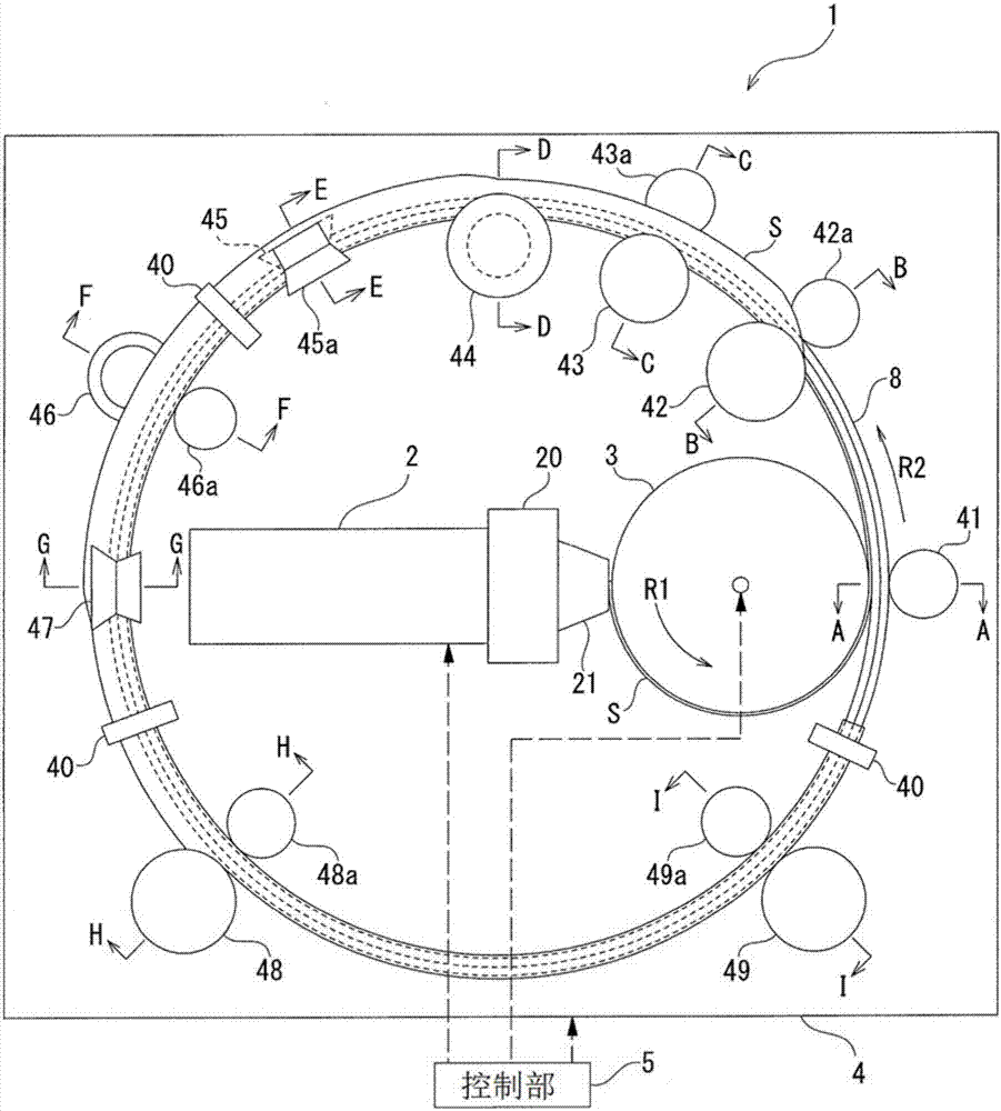
[0111] figure 1 It is a schematic diagram showing an example of the structure of the bead core covering device 1 . The bead core coating device 1 includes an extruder 2 , a rotary drum 3 , a covering device 4 , and a control unit 5 that controls the extruder 2 , the rotating drum 3 , and the covering device 4 .

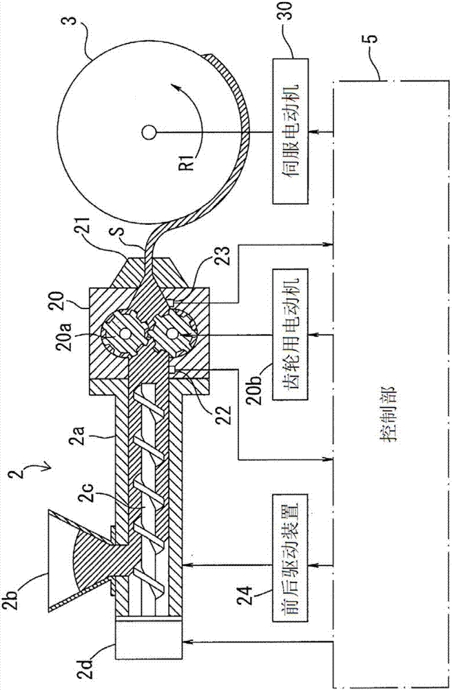
[0112] figure 2 It is a schematic diagram showing an example of the structure of the extruder 2 and the rotary drum 3 . The extruder 2 has: a cylindrical barrel 2a; a hopper 2b connected to a supply port of the barrel 2a; a screw 2c for kneading rubber and feeding it to the front end; and a screw motor 2d for rotationally driving the screw 2c. The rotation speed of the screw motor 2 d is controlled by the controller 5 as follows.

[0113] The front end side of the extruder 2 in the extrusion direction is connected to the gear pump 20 , and the front end side of the gear pump 20 is connected to the die 21 . The rubber material kneaded by the extruder 2 is supplied...

Embodiment approach

[0147] (1) In the first embodiment, the central portion in the width direction of the rubber sheet S wound on the outer peripheral surface of the rotary drum 3 is pasted on the inner periphery of the rotating bead core 8 from the front end. An example of the surface (lower surface 8a), but not limited thereto.

[0148] For example, if Figure 5 As shown, the rotating drum 3 may be arranged on the outer peripheral side of the bead core 8, and the center portion in the width direction of the rubber sheet S wound on the outer peripheral surface of the rotating drum 3 may be attached to the rotating bead core from the front end. 8 outer peripheral surface. According to this configuration, the structure of the equipment layout is simple, and it is also possible to easily cope with a dimensional change of the bead core.

[0149] In addition, the rotating drum 3 may be disposed on the side of the bead core 8, and the center portion in the width direction of the rubber sheet S wound...

no. 2 approach

[0152] Image 6 It is a schematic diagram showing an example of the structure of the bead core covering device 1 . The bead core coating device 1 includes an extruder 2 , a rotary drum 3 , a covering device 4 , and a control unit 5 that controls the extruder 2 , the rotating drum 3 , and the covering device 4 .

[0153] Figure 7 It is a figure which looked at the rotating drum 3 from the direction perpendicular|vertical to a rotation axis. The outer surface of the rotary drum 3 is formed with a circumferential groove 31 extending in the circumferential direction. The cross-sectional shape of the circumferential groove 31 in the axial direction of the rotary drum 3 is an inverted trapezoidal shape. The circumferential groove 31 includes a groove bottom surface 31 a and groove wall surfaces 31 b and 31 c extending from both sides of the groove bottom surface 31 a.

[0154] The cover device 4 supports the bead core 8 at a position downstream of the extruder 2 in the rotation...


PUM


Abstract

A bead core covering method for covering an annular bead core (8) with a belt-like rubber sheet (S) includes winding the rubber sheet (S) extruded by an extruding machine (2) via a mouth piece (21) around an outer peripheral surface of a rotary drum (3) from a leading end portion, attaching a part in a width direction of the rubber sheet (S) on the outer peripheral surface of the rotary drum (3) to an outer surface of the bead core (8), which rotates, from the leading end portion before the rubber sheet is wound over an entire periphery of the outer peripheral surface of the rotary drum (3), and wrapping a remaining portion in the width direction of the rubber sheet (S) attached to the outer surface of the bead core (8) along a cross-sectional shape of the bead core (8).

Description

technical field [0001] The present invention relates to a bead core covering method and a bead core covering device for covering an annular bead core with a strip-shaped rubber sheet. Background technique [0002] Generally, an annular bead core in which a converging body such as a steel wire is rubber-coated is arranged in a bead portion of a pneumatic tire. The surface of the bead core is sometimes covered with a thin rubber sheet in order to integrate steel wires and the like. This rubber sheet is also referred to as covering rubber or bead covering rubber. [0003] Patent Document 1 below describes a bead core covering device and a bead core covering method in which a sheet member made of rubber covers the surface of a bead core. The bead core covering device of Patent Document 1 includes: a supply unit that supplies a strip-shaped sheet member that covers the surface of the bead core to a rotating bead core; a forming roller that rotates in the direction of rotation o...

Claims


Application Information

Patent Timeline
Patent Type & Authority Applications(China)
IPC IPC(8): B29D30/50
CPCB29D30/50B29D2030/482
Inventor 桥本贺贵宫本亮史阿部正义
Owner TOYO TIRE & RUBBER CO LTD
Why Eureka
Try Eureka