Sludge reduction reaction system and treatment method

A technology of reaction system and treatment method, applied in the field of sludge reduction reaction system and treatment, can solve the problems of unfavorable large-scale popularization and application, low efficiency of ozone utilization, complex equipment structure, etc., and achieve simple structure, small footprint, The effect of high reaction efficiency

Pending Publication Date: 2017-11-03
江苏浦坤纳米科技有限公司
View PDF5 Cites 3 Cited by
  • Summary
  • Abstract
  • Description
  • Claims
  • Application Information

AI Technical Summary

Problems solved by technology

[0005] However, because ozone exists in the form of gas, there are gas-solid, solid-liquid and other mass transfer problems in the oxidation process of sludge, which makes the utilization efficiency of ozone low, so that it is sub

Method used


Image

  • Sludge reduction reaction system and treatment method
  • Sludge reduction reaction system and treatment method

Examples


Embodiment 1

[0039] In this embodiment, sludge reduction is carried out aiming at the low dosage of ozone in the reaction tank 4 .

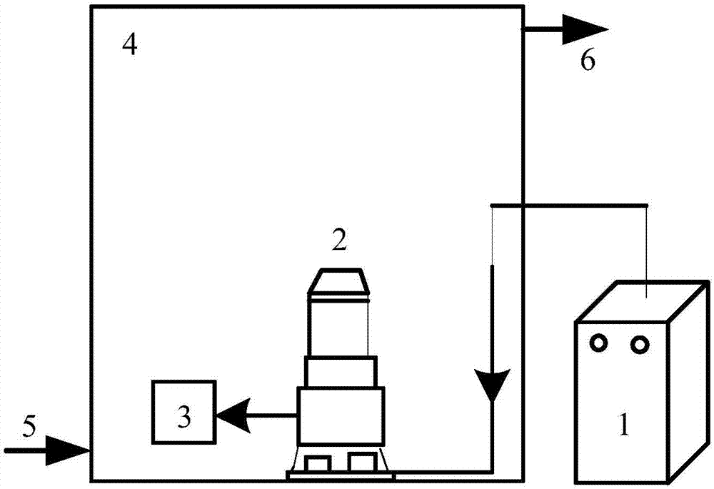
[0040] The 30g / h ozone generator 1 is installed outside the 30L reaction tank 4, and the submersible sewage pump 2 and releaser 3 are installed inside the reaction tank 4. A sludge inlet 5 is connected to the bottom of the reaction tank 4, and a sludge outlet 6 is connected to the upper part.

[0041] The gas outlet of the ozone generator 1 is connected to the inlet of the submersible sewage pump 2 through a trachea, and the outlet of the submersible sewage pump 2 is connected to the inlet of the releaser 3 .

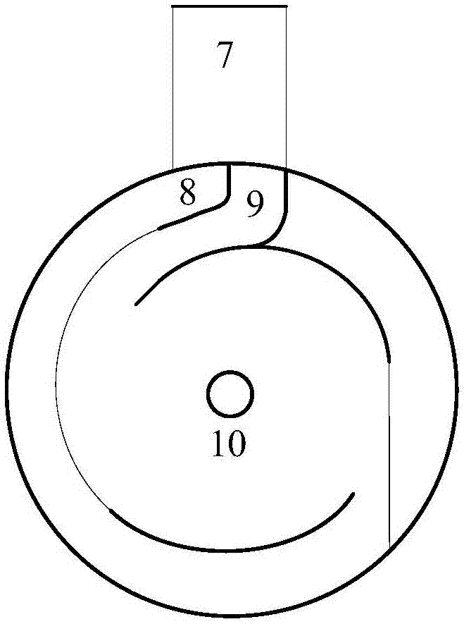
[0042] The sludge with MLSS concentration of 14.14g / L is filled with the reaction tank 4, and then the sludge feeding is stopped. Then start the ozone generator 1 and the submersible sewage pump 2. The inlet of the submersible sewage pump 2 uses negative pressure to suck in ozone gas and sludge at the same time, mix in the pump to form a mixture of oz...

Embodiment 2

[0046] In this embodiment, sludge reduction is carried out by increasing the dosage of ozone in the reaction tank 4 .

[0047] The 25.5g / h ozone generator 1 is installed outside the 40L reaction tank 4, and the submersible sewage pump 2 and the releaser 3 are installed inside the reaction tank 4. A sludge inlet 5 is connected to the bottom of the reaction tank 4, and a sludge outlet 6 is connected to the upper part.

[0048] The gas outlet of the ozone generator 1 is connected to the inlet of the submersible sewage pump 2 through a trachea, and the outlet of the submersible sewage pump 2 is connected to the inlet of the releaser 3 .

[0049] The sludge with MLSS concentration of 14.14g / L is filled with the reaction tank 4, and then the sludge feeding is stopped. Then start the ozone generator 1 and the submersible sewage pump 2. The inlet of the submersible sewage pump 2 uses negative pressure to suck in ozone gas and sludge at the same time, mix in the pump to form a mixture...

Embodiment 3

[0053] In this embodiment, sludge reduction is carried out by increasing the dosage of ozone in the reaction tank 4 .

[0054] The 30g / h ozone generator 1 is installed outside the 40L reaction tank 4, and the submersible sewage pump 2 and the releaser 3 are installed inside the reaction tank 4. A sludge inlet 5 is connected to the bottom of the reaction tank 4, and a sludge outlet 6 is connected to the upper part.

[0055] The gas outlet of the ozone generator 1 is connected to the inlet of the submersible sewage pump 2 through a trachea, and the outlet of the submersible sewage pump 2 is connected to the inlet of the releaser 3 .

[0056] The sludge with MLSS concentration of 14.14g / L is filled with the reaction tank 4, and then the sludge feeding is stopped. Then start the ozone generator 1 and the submersible sewage pump 2. The inlet of the submersible sewage pump 2 uses negative pressure to suck in ozone gas and sludge at the same time, mix in the pump to form a mixture o...


PUM


Abstract

The invention relates to a sludge reduction reaction system. The sludge reduction reaction system comprises a reaction tank, a submersible sewage pump, a releaser and an ozonizer, wherein the submersible sewage pump and the releaser are arranged in the reaction tank; the ozonizer is arranged outside the reaction tank; the reaction tank is provided with a sludge inlet and a sludge outlet; an ozone outlet of the ozonizer is connected with a gas inlet of the submersible sewage pump; a material flow inlet of the releaser is connected with the submersible sewage pump; the submersible sewage pump sucks sludge and ozone by negative pressure; the sludge and the ozone are mixed and then flow into the releaser; the material flow inlet, an arc-shaped material flow channel connected with the material flow inlet and a material flow orifice are formed in the releaser; the material flow channel is communicated with the orifice; material flows entering the releaser pass through the material flow channel and then are sprayed out by the orifice. The reaction system disclosed by the invention has the advantages of simple structure, small occupied area, investment saving, simple operation and high reaction efficiency; the ozone can be completely utilized, so that the use of an ozone destructor is avoided.

Description

technical field [0001] The invention relates to a sludge treatment system, in particular to a sludge reduction reaction system and a treatment method. Background technique [0002] Activated sludge process is the most widely used biological water treatment technology at home and abroad. One of its main problems is that it will produce a large amount of excess sludge. The investment and operation cost of the excess sludge treatment device accounts for about 25%-65% of the investment and operation cost of the whole sewage treatment plant. The huge sludge disposal cost has become a serious problem faced by sewage biological treatment technology. At present, sewage treatment plants generally use landfill and composting methods to treat sludge. However, these two methods will cause the heavy metal content in the soil to exceed the standard, which seriously threatens the human living environment. Therefore, how to adopt reasonable and effective technical means to deal with excess...

Claims


Application Information

Patent Timeline
IPC IPC(8): C02F11/06
CPCC02F11/06C02F2303/06
Inventor 杨庆峰陈崇友董康正
Owner 江苏浦坤纳米科技有限公司
Why Eureka
Try Eureka