Material spraying device for combusting and feeding biomass bagasse

A technology of biomass and material feeding, which is applied in the direction of combustion method, combustion equipment, fuel supply, etc., and can solve the problems of combustion in the furnace, incomplete combustion of bagasse, and reduction of boiler thermal efficiency.

Active Publication Date: 2017-11-03
GUANGDONG YUEWEI ENVIRONMENT TECH CO LTD
View PDF8 Cites 0 Cited by
  • Summary
  • Abstract
  • Description
  • Claims
  • Application Information

AI Technical Summary

Problems solved by technology

[0002] The existing feeding system in front of the furnace of the bagasse boiler is to discharge the material through the push-pull scraper device on the belt conveyor. After the bagasse enters the feeder, it is transported into the furnace through the feeding nozzle of the feeder for combustion. This is a traditional process with low conveying efficiency. At the same time, it is easy to cause bagasse to pile up in the feeding nozzle of the feeder, and then cause the bagasse to enter the furnace for combustion under the condition of piles. The piles of bagasse cannot be fully burned in the furnace. It greatly affects the combustion efficiency of the furnace. Since the bagasse cannot be fully burned, it will reduce the thermal efficiency of the boiler and increase the generation of nitrogen oxides during the combustion process and the increase in fuel costs.

Method used


Image

  • Material spraying device for combusting and feeding biomass bagasse
  • Material spraying device for combusting and feeding biomass bagasse
  • Material spraying device for combusting and feeding biomass bagasse

Examples


Embodiment 1

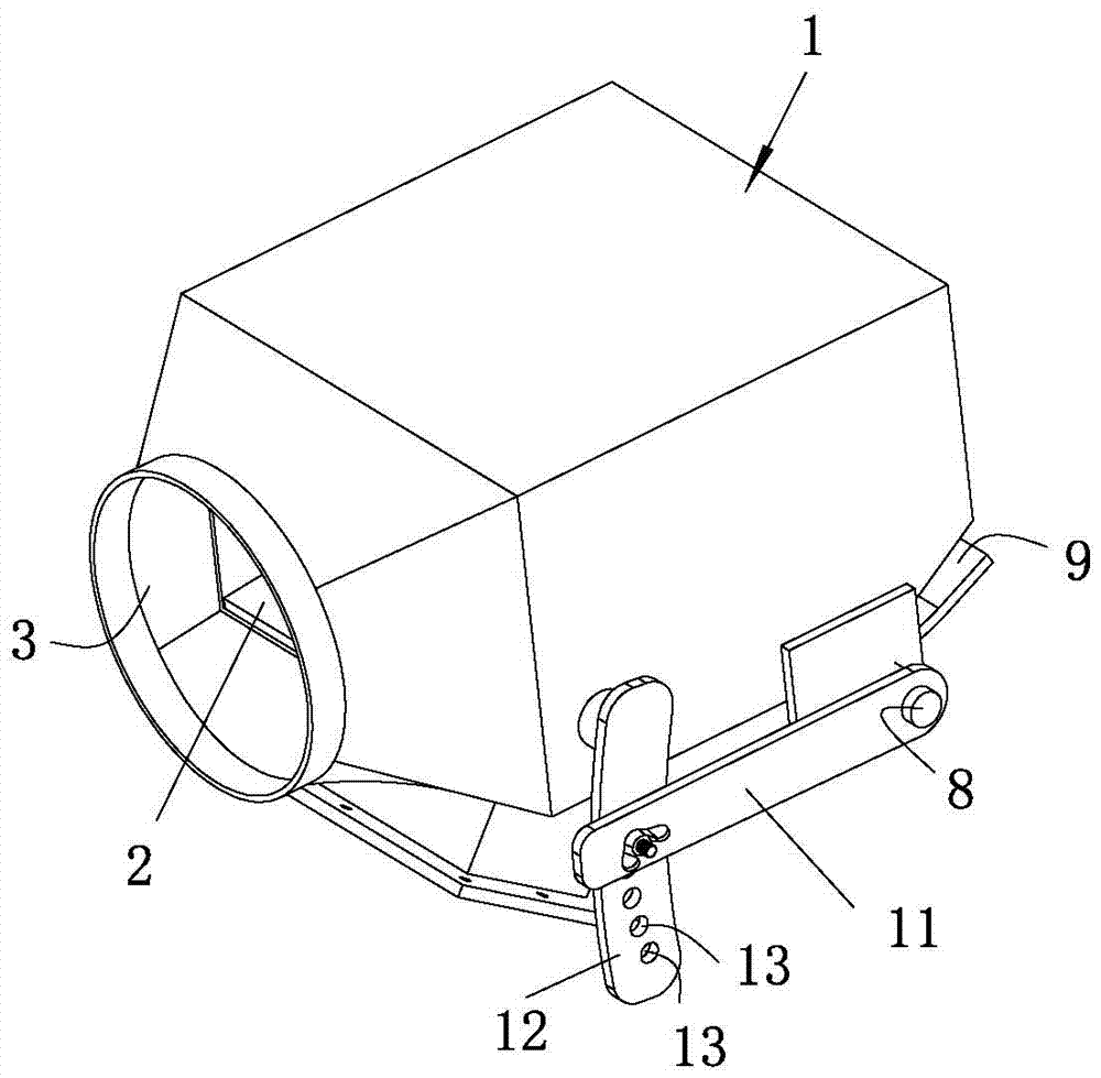
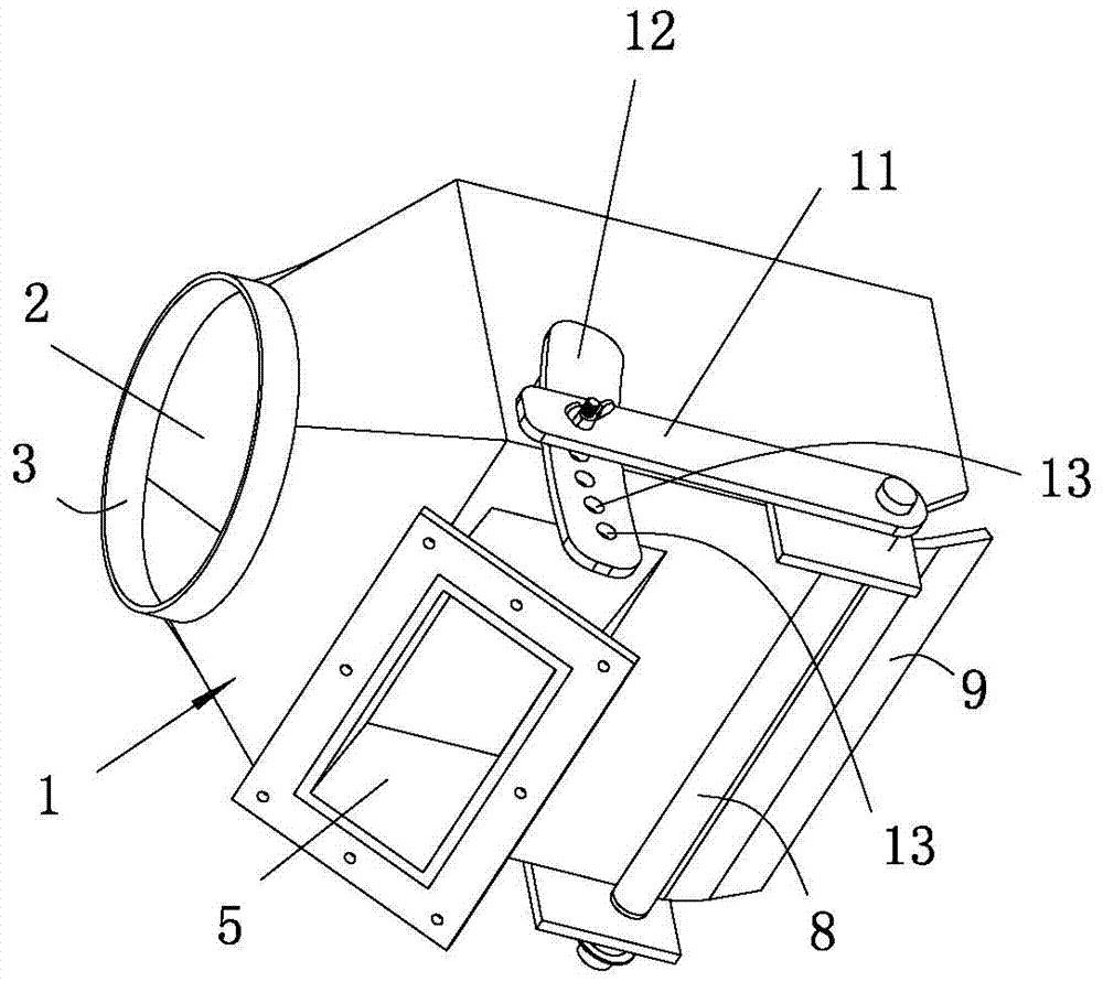
[0036] see Figure 1 to Figure 5 As shown, a feeder for biomass bagasse burning and feeding according to the present invention includes a housing 1, the housing 1 is provided with a feeding hole 2 penetrating through the housing 1, and the feeding hole 2 runs through the housing 1 along the left and right direction, The two ends of the feed hole 2 are respectively the feed port 3 and the discharge port 4. The housing 1 is also provided with an air inlet 5 connected to the feed hole 2. The end of the air inlet 5 away from the feed hole 2 is an air inlet. The end that the hole 5 communicates with the feed hole 2 is a communication port 6; the housing 1 is equipped with a sandwich plate 7 located in the feed hole 2, and the sandwich plate 7 blocks the communication between the feed port 3 and the communication port 6, and the air intake The hole 5 communicates with the discharge port 4 via the gap between the interlayer plate 7 and the housing 1 .

[0037] In actual use, the bio...

Embodiment 2

[0054] In this embodiment, preferably, the shell 1 is a metal alloy shell, and the metal alloy for the shell is composed of the following components by weight percentage: Cr 16%, Ni 8%, Si 2%, Mn 0.6%, Ti 0.02%, Sc 0.03%, Ce 0.1%, Nb 0.02%, Mo 0.02%, Cu 0.25%, P 0.02%, S 0.01%, N 0.12%, C 0.04%, and the balance is Fe.

[0055] Preferably, the preparation method of the metal alloy for the shell comprises the following steps:

[0056] (1) Add other components except Sc and Ce according to the above ratio, and melt in a vacuum induction furnace. After all the components are melted, add a deoxidizer Ca of 0.08% by weight of the alloy melt to deoxidize the alloy melt ; Add Sc and Ce alloy melts after deoxidation, and keep stirring for 3 minutes; after standing for 2 minutes, pour the alloy melt into a casting mold to form an ingot. Alloy ingots released;

[0057] (2) Forging the alloy ingot out of the furnace at a temperature of 1050°C; then hot rolling the forged alloy ingot at ...

Embodiment 3

[0062] In this embodiment, the shell 1 is a metal alloy shell, and the metal alloy for the shell is composed of the following components in weight percentage: Cr 18%, Ni 5%, Si 3%, Mn 0.2%, Ti-0.04% , Sc 0.06%, Ce0.05%, Nb 0.04%, Mo0.01%, Cu 0.35%, P 0.01%, S 0.02%, N 0.08-0.12%, C 0.0.07%, and the balance is Fe.

[0063] Preferably, the preparation method of the metal alloy for the shell comprises the following steps:

[0064] (1) Add other components except Sc and Ce according to the above ratio, and melt in a vacuum induction furnace. After all the components are melted, add a deoxidizer Ca of 0.15% by weight of the alloy melt to deoxidize the alloy melt. ; Add Sc and Ce alloy melts after deoxidation, and stir continuously for 5 minutes; after standing for 4 minutes, pour the alloy melt into a casting mold to form an ingot. The casting temperature is 1600 ° C. After the mold is cooled, the Alloy ingots released;

[0065] (2) Forging the alloy ingot out of the furnace at a...


PUM


Abstract

The invention relates to the technical field of material supply devices and in particular discloses a material spraying device for combusting and feeding biomass bagasse. The material spraying device comprises a shell body, wherein the shell body is internally provided with a feeding hole penetrating through the shell body; a feeding opening and a discharging opening are formed in two ends of the feeding hole respectively; the shell body is further provided with an air inlet hole communicated with the feeding hole; an air inlet is formed in one end, far away from the feeding hole, of the air inlet hole; a communication opening is formed in one end, communicated with the feeding hole, of the air inlet hole; the shell body is provided with an interlayer plate located in the feeding hole; the interlayer plate is used for separating the communication between the feeding opening and the communication opening; the air inlet hole is communicated with the discharging opening through a gap between the interlayer plate and the shell body; when the material spraying device is actually utilized, the biomass bagasse to be combusted is conveyed into the feeding hole through the feeding opening and external air enters the shell body through the air inlet hole; the biomass bagasse in the feeding hole is sprayed into a boiler so that the biomass bagasse is dispersed in the boiler and a condition that the biomass bagasse enters the boiler for combustion in a pile manner is prevented; and the combustion efficiency of the biomass bagasse is improved and the generation of low-nitrogen oxide is reduced.

Description

technical field [0001] The invention relates to the technical field of material feeders, and in particular discloses a feeder for burning and feeding biomass bagasse. Background technique [0002] The existing feeding system in front of the furnace of the bagasse boiler is to discharge the material through the push-pull scraper device on the belt conveyor. After the bagasse enters the feeder, it is transported into the furnace through the feeding nozzle of the feeder for combustion. This is a traditional process with low conveying efficiency. At the same time, it is easy to cause bagasse to pile up in the feeding nozzle of the feeder, and then cause the bagasse to enter the furnace for combustion under the condition of piles. The piles of bagasse cannot be fully burned in the furnace. It greatly affects the combustion efficiency of the furnace. Since the bagasse is not fully burned, it will reduce the thermal efficiency of the boiler and increase the amount of nitrogen oxide...

Claims


Application Information

Patent Timeline
Patent Type & Authority Applications(China)
IPC IPC(8): F23K3/00
CPCF23K3/00F23K2203/20
Inventor 裴志鑫裴恒信裴恒勇曾庆东廖学杰
Owner GUANGDONG YUEWEI ENVIRONMENT TECH CO LTD
Why Eureka
Try Eureka