Liquid metal purification experiment loop system and application method thereof

A liquid metal and experimental loop technology, applied in chemical instruments and methods, chemical/physical processes, melting, etc., can solve the problem of easy blockage of heat exchanger flow channels and loop pipes, high operating costs of corrosion loops, and reduced heat transfer efficiency, etc. problems, to achieve the effect of improving the efficiency of purification experiments, shortening the time of purification experiments, and improving the efficiency of experiments

Active Publication Date: 2017-11-03
BAISE UNIV
View PDF9 Cites 9 Cited by
  • Summary
  • Abstract
  • Description
  • Claims
  • Application Information

AI Technical Summary

Problems solved by technology

In liquid metal reactors or loops, an important problem is that the corrosion of structural materials by liquid metal is likely to cause impurities, and impurities may also be introduced during maintenance, loading and unloading, or raw materials, and these impurities are likely to block the flow channels of the heat exchanger. and loop piping, reducing heat transfer efficiency, etc.
[0003] In order to ensure the safe operation of the loop and reactor, the coolant must be purified, but the current purification technology is immature, so it is necessary to purify the loop for experiments. Usually, the purification experiment is carried out in the corrosion test loop, but due to the high operating cost of the corrosion loop, the experiment The cost is high, and the source of impurities in the liquid metal is mainly caused by the liquid metal corroding the pipeline for a long time, the experiment time is long and the efficiency is low

Method used


Image

  • Liquid metal purification experiment loop system and application method thereof

Examples


Embodiment Construction

[0026] The present invention will be further described below in conjunction with the accompanying drawings and embodiments.

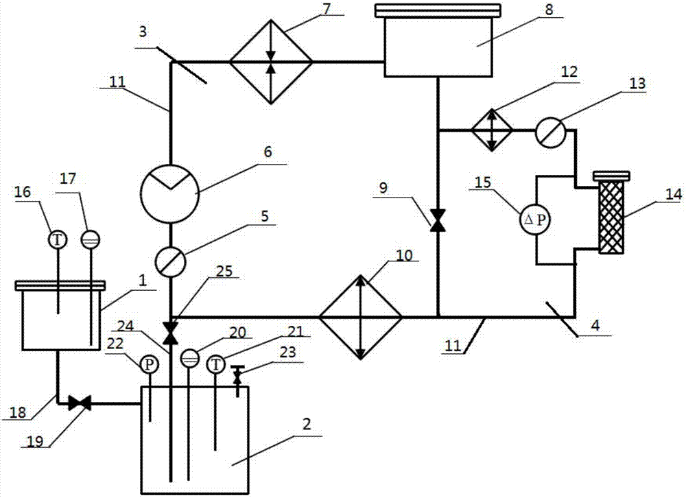
[0027] see figure 1 , a liquid metal purification experiment circuit system, including a melting tank 1, a storage tank 2 and a circuit body, the circuit body includes a main circuit unit 3 and a purification branch unit 4; the main circuit unit 3 includes a flowmeter 5, a pump 6, a heating Device 7, expansion tank 8, valve one 9 and cooler one 10, flow meter one 5 are connected with electromagnetic pump 6, heater 7, expansion tank 8, valve one 9 and cooler one 10 through pipeline 11 to form the main circuit 3 The pipeline 11 at valve one 9 two ends is provided with purification branch circuit unit 4 in parallel, and purification branch circuit 4 comprises cooler two 12, flow meter two 13 and purification experimental device 14 that are serially connected in sequence, and one end of cooler two 12 is connected through pipeline Between the expansion tank...


PUM


Abstract

The invention belongs to the technical field of liquid metal purification and discloses a liquid metal purification experiment loop system. The liquid metal purification experiment loop system comprises a melting tank, a storage tank and a loop body; the loop body comprises a main loop unit and a purification branch unit; the main loop unit comprises a first flowmeter, a pump, a heater, an expansion box, a first valve and a first cooler which are sequentially connected to form a loop, the purification branch unit comprises a second cooler, a second flowmeter and a purification experiment device which are serially connected in sequence, a first thermocouple and a first liquidometer are arranged at the top of the melting tank, the bottom of the melting tank is connected with the upper portion of the storage tank through a first connecting pipe, and a second valve is arranged on the first connecting pipe; a second liquidometer, a second thermocouple, a pressure meter and a gas circuit interface are arranged at the top of the storage tank. By the arrangement, purification experiments can be carried out, and true working condition can be simulated by adding impurities to the expansion box; in addition, operation cost is low, experiment efficiency is high, convenience in use is achieved, and the experiments on various filter cores can be performed.

Description

technical field [0001] The invention belongs to the technical field of liquid metal purification, and in particular relates to a liquid metal purification experimental loop system and a use method thereof. Background technique [0002] Because of its low melting point, high boiling point, and good thermal conductivity, liquid metal has become the first choice for the coolant of a new generation of liquid metal reactors. For example, lead is used as coolant in lead-based reactors, and lead-bismuth alloy is used as coolant in accelerator-driven subcritical systems. Extensive research has been carried out worldwide. In liquid metal reactors or loops, an important problem is that the corrosion of structural materials by liquid metal is likely to cause impurities, and impurities may also be introduced during maintenance, loading and unloading, or raw materials, and these impurities are likely to block the flow channels of the heat exchanger. And loop pipes, reduce heat transfer ...

Claims


Application Information

Patent Timeline
Patent Type & Authority Applications(China)
IPC IPC(8): G01N33/00G01L13/00B01J6/00
CPCB01J6/005G01L13/00G01N33/00G01N2033/0088Y02E30/30
Inventor 徐敬尧周小丽
Owner BAISE UNIV
Why Eureka
Try Eureka